
Automatic monitoring method for pre-compressed optical fiber sensing settlement of cast-in-place beam supports

An optical fiber sensing and automatic monitoring technology, applied in the direction of hydrostatic pressure, etc., can solve the problems of unguaranteed personal safety of surveyors, inaccurate assessment of potential safety hazards, slowing down the progress of the project, etc., so as to avoid damage from lightning strikes. and electromagnetic interference, reducing manual operation, and reducing the effect of observation errors

Inactive Publication Date: 2019-08-23
CR10BG NO 3 CONSTR
View PDF6 Cites 2 Cited by
  • Summary
  • Abstract
  • Description
  • Claims
  • Application Information

AI Technical Summary

Problems solved by technology

[0005] Aiming at the deficiencies of the prior art, the present invention provides an automatic monitoring method for pre-compressed optical fiber sensing settlement of cast-in-place beam supports, which solves the problem of low efficiency and waste of a lot of manpower and material resources in traditional methods for bridge settlement, and insufficient measurement accuracy. The assessment of safety hazards is not accurate enough and the personal safety of surveyors cannot be guaranteed during the measurement process, which greatly slows down the progress of the project

Method used


Image

  • Automatic monitoring method for pre-compressed optical fiber sensing settlement of cast-in-place beam supports
  • Automatic monitoring method for pre-compressed optical fiber sensing settlement of cast-in-place beam supports
  • Automatic monitoring method for pre-compressed optical fiber sensing settlement of cast-in-place beam supports

Examples


Embodiment Construction

[0025] The following will clearly and completely describe the technical solutions in the embodiments of the present invention with reference to the accompanying drawings in the embodiments of the present invention. Obviously, the described embodiments are only some, not all, embodiments of the present invention. Based on the embodiments of the present invention, all other embodiments obtained by persons of ordinary skill in the art without making creative efforts belong to the protection scope of the present invention.

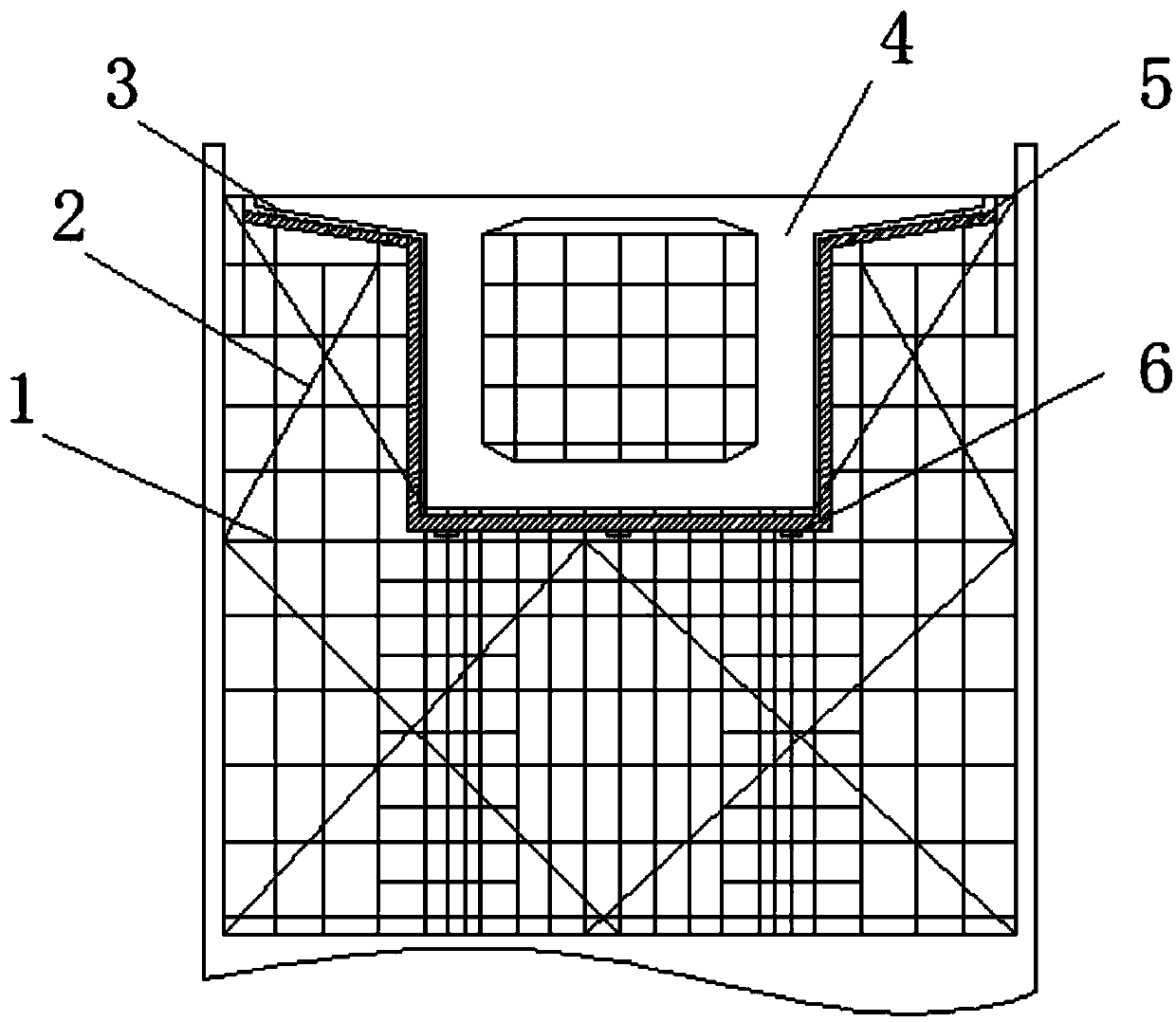
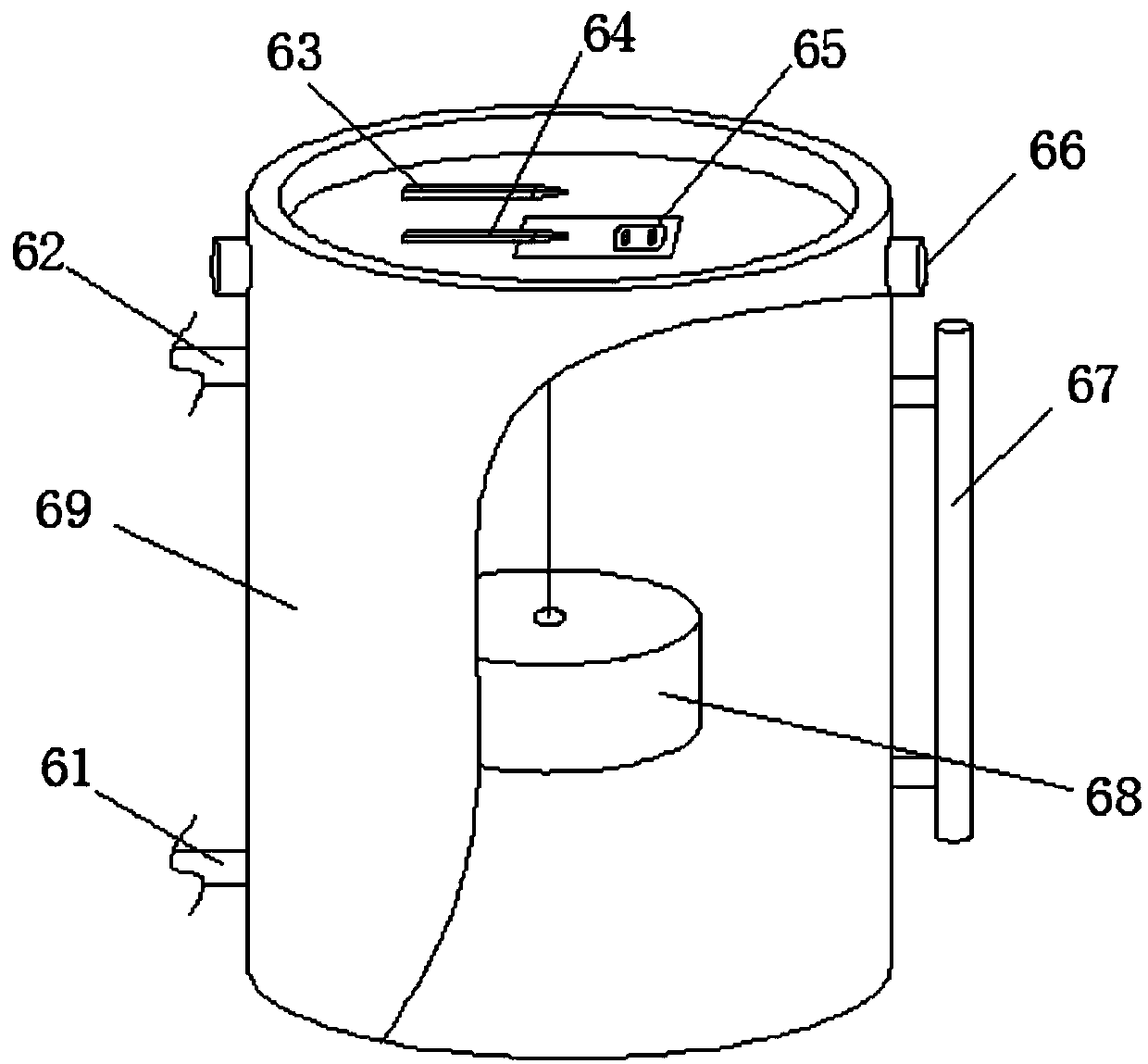
[0026] An embodiment of the present invention provides an automatic monitoring method for pre-compressed optical fiber sensing settlement of cast-in-place beam supports, such as Figure 1-3 As shown, it includes the beam body 4 and the steel pipe support 1 installed at the bottom of the beam body 4. The inside of the steel pipe support 1 is also equipped with a scissors brace 2 for reinforcement, and an I-beam 5 is laid between the steel pipe support 1 and the ...


PUM


Abstract

The invention discloses an automatic monitoring method for pre-compressed optical fiber sensing settlement of cast-in-place beam supports. A beam body and a steel pipe support installed at the bottomof the beam body are included; a cross bracing used for reinforcing is installed at the internal of the steel pipe support; I-steel is paved between the steel pipe support and the beam body; longitudinal square timber is paved between the I-steel and the beam body; the center position of the beam body is pre-provided with a bridge doorway; static levels are installed at the positions, corresponding to the bridge doorway, of the longitudinal square timber at the bottom of the beam body; and the static levels and the longitudinal square timber are fixed together through three threaded support rods. Through the introduction of an optical fiber sensing real-time automatic monitoring technology, support pre-compressed settlement monitoring work can be developed, manual operation can be reduced,working efficiency can be enhanced, and power is not supplied on site, lightning stroke damages and electromagnetic interference can be avoided; the method is good in stability and strong in anti-interference capability; and the method is small in influence caused by extraneous environments and convenient for installation and monitoring in the open air and in fields.

Description

technical field [0001] The invention relates to the technical field of optical fiber sensing settlement monitoring, in particular to an automatic monitoring method for preloading optical fiber sensing settlement of cast-in-place beam supports. Background technique [0002] As an agricultural country with a large population, the per capita land area is decreasing day by day due to environmental pollution. In order to solve the land for people's survival and the traffic problems in some special places, various places have to be classified as construction sites for civil engineering , Civil engineering includes the planning, construction and maintenance of all infrastructure related to water, soil and culture. At present, general civil engineering projects include housing, roads, waterworks, drainage, flood control and transportation. In the past, all non-military civil engineering projects were classified into this category, but as engineering science becomes more and more ex...

Claims


Application Information

Patent Timeline
Patent Type & Authority Applications(China)
IPC IPC(8): G01C5/04
CPCG01C5/04
Inventor 刘伟高虎王伟
Owner CR10BG NO 3 CONSTR
Learn More