Thoracic surgery nursing drainage device

A thoracic surgery and suction pump technology, applied in the field of thoracic surgery nursing and drainage devices, can solve the problems of effusion export, difficulty in controlling the pulling force of effusion, and endangering the patient's condition recovery, etc., and achieves the effect of reducing workload and facilitating detection and positioning.

Inactive Publication Date: 2019-08-23
刘君
View PDF1 Cites 1 Cited by
  • Summary
  • Abstract
  • Description
  • Claims
  • Application Information

AI Technical Summary

Problems solved by technology

[0002] After the internal operation of the patient's thoracic cavity, pleural effusion will be generated inside the pleural cavity, and the effusion will seriously endanger the recovery of the patient's condition. Therefore, it is necessary to discharge the pleural effusion in time. The current thoracic surgery nursing drainage device cannot adjust the relative position. It is very easy to cause damage to the inner end of the patient's thoracic cavity, and it will increase the workload of the nurses, and it is impossible to conveniently export the effusion. For example, the patent application publication number 201520925764.1 discloses a nursing drainage device for thoracic surgery, which includes a fixed box, a miniature Pumps, control switches, pumping tubes, plugs, connecting tubes, needles, drain tubes, effusion bottles, and protective covers. However, during the use of the above patents, the relative position cannot be adjusted. The pulling force of the effusion is difficult to control, and it is extremely easy It will cause damage to the inner end of the patient's thoracic cavity, and will increase the workload of the nursing staff, making it impossible to export the effusion conveniently

Method used


Image

  • Thoracic surgery nursing drainage device
  • Thoracic surgery nursing drainage device
  • Thoracic surgery nursing drainage device

Examples


Embodiment Construction

[0015] The technical solutions in the embodiments of the present invention will be clearly and completely described below in conjunction with the accompanying drawings in the embodiments of the present invention. Obviously, the described embodiments are only a part of the embodiments of the present invention, rather than all the embodiments. Based on the embodiments of the present invention, all other embodiments obtained by those of ordinary skill in the art without creative work shall fall within the protection scope of the present invention.

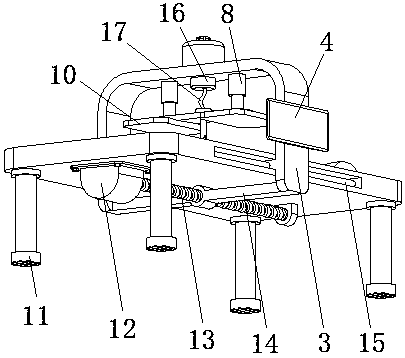
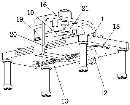
[0016] See Figure 1-3 , The present invention provides a technical solution: a thoracic surgery nursing drainage device, comprising a bed body 1, the lower side of the bed body 1 is provided with more than four sets of equidistant and symmetrically distributed uprights 5, the ends of the uprights 5 away from the bed body 1 are all A non-slip mat 11 is connected. The upper side of the bed body 1 is provided with a neck pillow 6 to protec...


PUM


Abstract

The invention discloses a thoracic surgery nursing drainage device which comprises a bed body. Two sliding grooves are formed in the two sides of the bed body, sliding shafts are arranged at the middle positions in the sliding grooves, sliding blocks are arranged at the middle positions of the sliding shafts, a bracket plate is arranged on the sides, away from the bed body, of the sliding blocks,a connecting rod is arranged on the lower side of the bracket plate, a servo motor is arranged on the lower side of the bed body, the side, close to the servo motor, of the bed body is connected witha motor fixing plate through hexagon bolts, an output shaft of the servo motor is connected with one end of a rotating shaft through a coupler, and the other end of the rotating shaft is connected with a lead screw. The bracket plate moves in the axial direction of the sliding shafts through thread transmission between the lead screw and the connecting rod, thus, the relative position can be adjusted, and the workload of nursing staff can be reduced; through a CT fluoroscopy instrument, the drainage position can be conveniently detected and determined; by using a negative-pressure suction pumpin cooperation with a liquid guide hose and a drainage cannula, effusion can be conveniently guided out.

Description

Technical field [0001] The invention relates to the technical field of medical equipment, in particular to a nursing drainage device for thoracic surgery. Background technique [0002] The patient’s internal thoracic cavity surgery will cause effusion in the pleural cavity, and the effusion will seriously harm the patient’s recovery. Therefore, it is necessary to drain the pleural effusion in time. The current thoracic surgery nursing drainage device cannot adjust the relative position. It is very easy to cause damage to the inner end of the patient’s thoracic cavity and increase the workload of the nursing staff, making it impossible to easily drain the effusion. For example, the patent application publication number 201520925764.1 discloses a thoracic surgery nursing drainage device, including a fixed box, a mini Pumps, control switches, pumping pipes, plugs, connecting pipes, needles, drain pipes, effusion bottles, protective caps, but the above patents cannot adjust the relat...

Claims


Application Information

Patent Timeline
Patent Type & Authority Applications(China)
IPC IPC(8): A61M1/00A61M25/08
CPCA61M1/0023A61M25/01A61M2025/0177A61M1/84
Inventor 刘君王启飞
Owner 刘君
Why Eureka
Try Eureka