
Implantable antenna system

An antenna system and antenna assembly technology, which is applied to the antenna grounding device, the structural connection of the antenna grounding switch, the structural form of the radiating element, etc., can solve the problems of increasing patient pain, short transmission distance, and short working life, and achieve miniaturization, The effect of reducing the size of the antenna and reducing the footprint

Active Publication Date: 2019-08-20
NANJING UNIV OF POSTS & TELECOMM
View PDF15 Cites 2 Cited by
  • Summary
  • Abstract
  • Description
  • Claims
  • Application Information

AI Technical Summary

Problems solved by technology

Traditional medical implants use low-frequency inductive coils for communication. This method has disadvantages such as large size, slow transmission rate, and short transmission distance. Therefore, researchers use radio frequency implantable antennas instead of inductive coils to solve the above problems.
However, at present, implantable antennas are powered by batteries, which are large in size and short in working life. Frequent replacement of batteries will inevitably increase the pain of patients. Using multi-band implantable antennas can realize other functions such as wireless charging while communicating

Method used


Image

  • Implantable antenna system
  • Implantable antenna system
  • Implantable antenna system

Examples


Embodiment Construction

[0027] In order to make the technical means, creative features, goals and effects achieved by the present invention easy to understand, the present invention will be further described below in conjunction with specific embodiments.

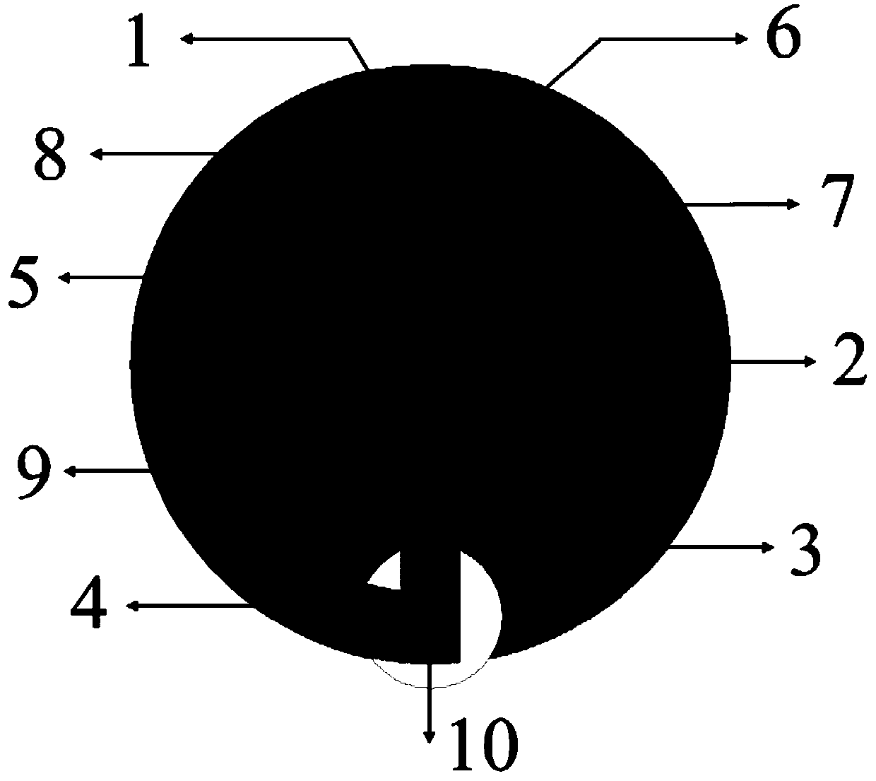
[0028] Such as Figure 1 to Figure 3 Shown, an implantable antenna system, the system is suitable for the human environment. The antenna structure is built on the medium surface of the plane dielectric board 212, connected to the metal grounding plate 9 through the short-circuit nail 7 and the short-circuit nail 28, and covered with a plane dielectric board-11 with the same thickness and material to separate the antenna from the skin tissue open. The antenna adopts coaxial feeding, and the feeding point 10 is located at a distance of 4mm from the center of the circle to the strip metal strip 1 .

[0029] The patch consists of two mutually perpendicular strip metal strips one 1 and strip metal strip two 2 and four connected arc metal strips one 3...


PUM


Abstract

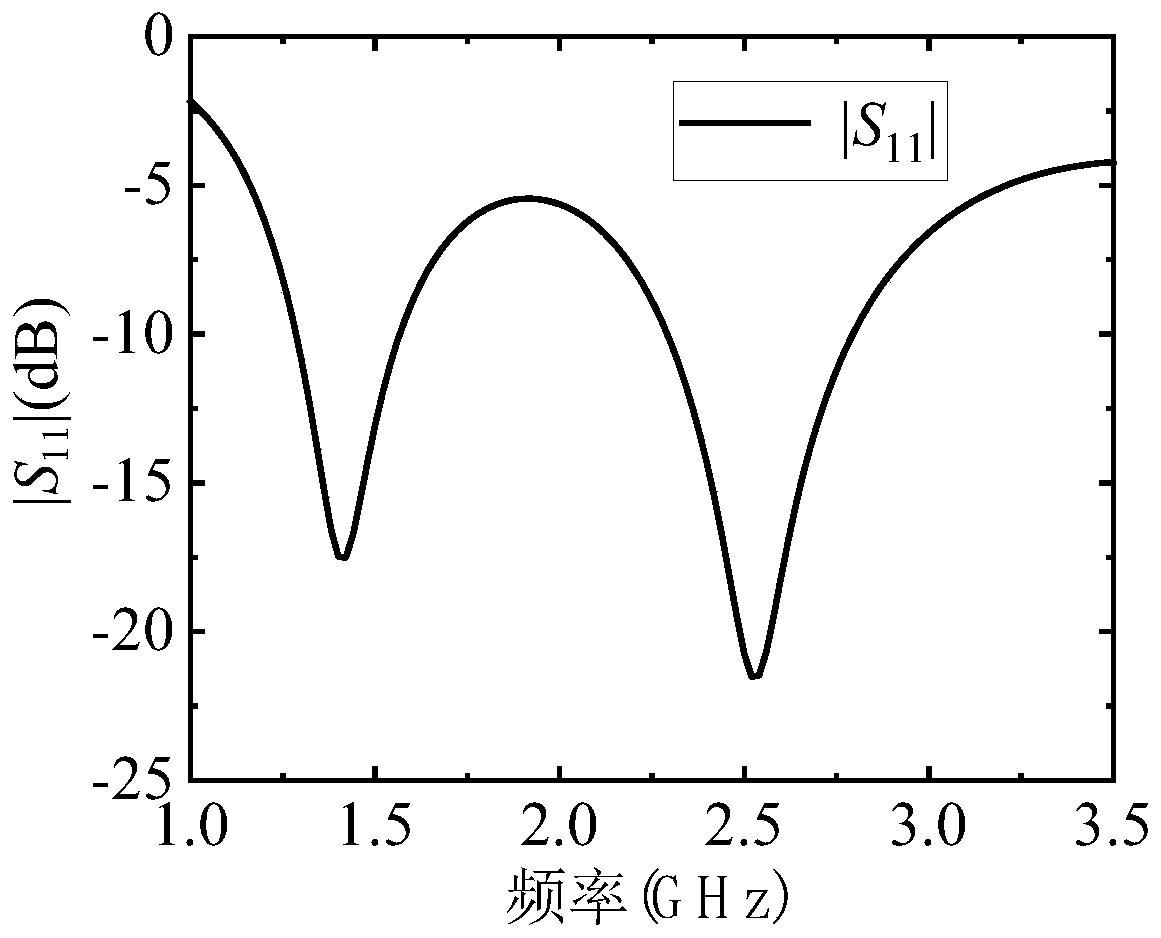
The invention discloses an implantable antenna system. Firstly, double layers of circular Rogers dielectric substrates with the same thickness and size are adopted, the diameter of each circular Rogers dielectric substrate is the same as the diameter of a patch antenna and the diameter of a metal grounding plate, and coaxial feeding is conducted through the bottom. The patch antenna is arranged between the two layers of dielectric substrates and is composed of two metal bands and four arc-shaped metal bands which are perpendicular to each other, and two adjacent arc-shaped metal bands are respectively provided with short circuit nails to be connected with the ground, so that the following effects are achieved: the size of the antenna is greatly reduced while a current path is increased, and miniaturization is better realized; and different resonant modes are excited, the feed position is adjusted to realize a dual-band resonant effect, and the radiation bandwidth and the radiation efficiency are increased.

Description

technical field [0001] The invention relates to the technical field of wireless communication, and in particular relates to an implantable antenna system. [0002] Background technique: [0003] With the rapid development of wireless communication technology and the electronic industry, medical implantable electronic devices are widely used in disease treatment and physiological detection, providing a lot of convenience for patients' lives. Traditional medical implants use low-frequency inductive coils for communication. This method has disadvantages such as large size, slow transmission rate, and short transmission distance. Therefore, researchers use radio frequency implantable antennas instead of inductive coils to solve the above problems. However, at present, implantable antennas are powered by batteries, which are large in size and short in working life. Frequent replacement of batteries will inevitably increase the pain of patients. Using multi-band implantable antenna...

Claims


Application Information

Patent Timeline
Patent Type & Authority Applications(China)
IPC IPC(8): H01Q1/36H01Q1/38H01Q1/48H01Q1/50
CPCH01Q1/36H01Q1/38H01Q1/48H01Q1/50
Inventor 许丽洁储昭俊汤一铭祝雷
Owner NANJING UNIV OF POSTS & TELECOMM
Learn More