Flexible multi-point transmission device

A kind of transmission device and flexible technology, which is applied in the direction of transmission device, transmission device parts, belt/chain/gear, etc., can solve the problems of high manufacturing cost, affecting the improvement of enterprise productivity, and high energy consumption in operation, so as to achieve simple structure, Reasonable design, the effect of improving equipment work efficiency and productivity

Pending Publication Date: 2019-08-20
无锡恒久安泰智能制造有限公司
View PDF0 Cites 0 Cited by
  • Summary
  • Abstract
  • Description
  • Claims
  • Application Information

AI Technical Summary

Problems solved by technology

[0002] As a pillar industry of our country, the manufacturing industry has always maintained a good development trend. Emerging technologies are constantly being applied in production practice. On the premise of realizing their basic functions, the manufactured equipment is gradually becoming intelligent, informatized, serialized, and efficient. At the same time, the support device for workpiece processing is required to be fast, convenient and safe, and it is even stricter for the transmission device; the change of the support device takes up a lot of non-processing man-hours, which affects the improvement of enterprise productivity.
Most of the existing equipment adopts the method of replacing the supporting device to realize the production change, and each actuator is equipped with a power source for power transmission, which leads to high equipment manufacturing costs and high energy consumption in operation

Method used


Image

  • Flexible multi-point transmission device
  • Flexible multi-point transmission device
  • Flexible multi-point transmission device

Examples


Embodiment Construction

[0018] The following will clearly and completely describe the technical solutions in the embodiments of the present invention with reference to the accompanying drawings in the embodiments of the present invention. Obviously, the described embodiments are only some of the embodiments of the present invention, not all of them. Based on the embodiments of the present invention, all other embodiments obtained by persons of ordinary skill in the art without making creative efforts belong to the protection scope of the present invention.

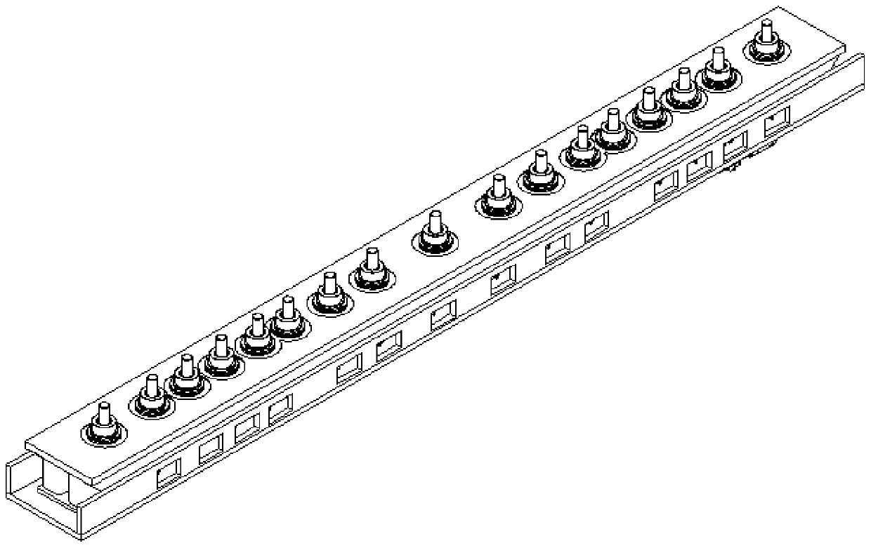
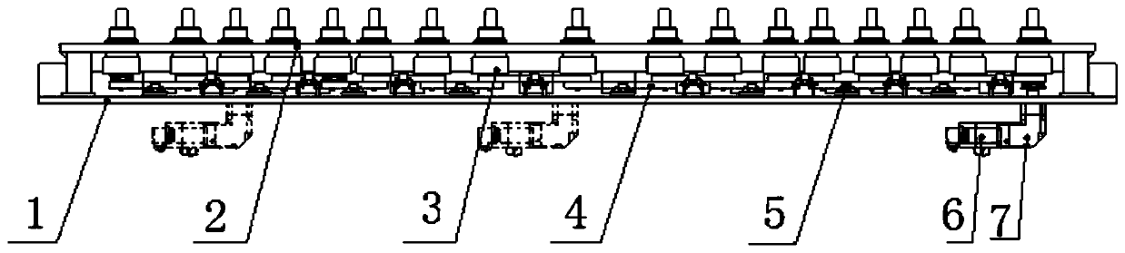
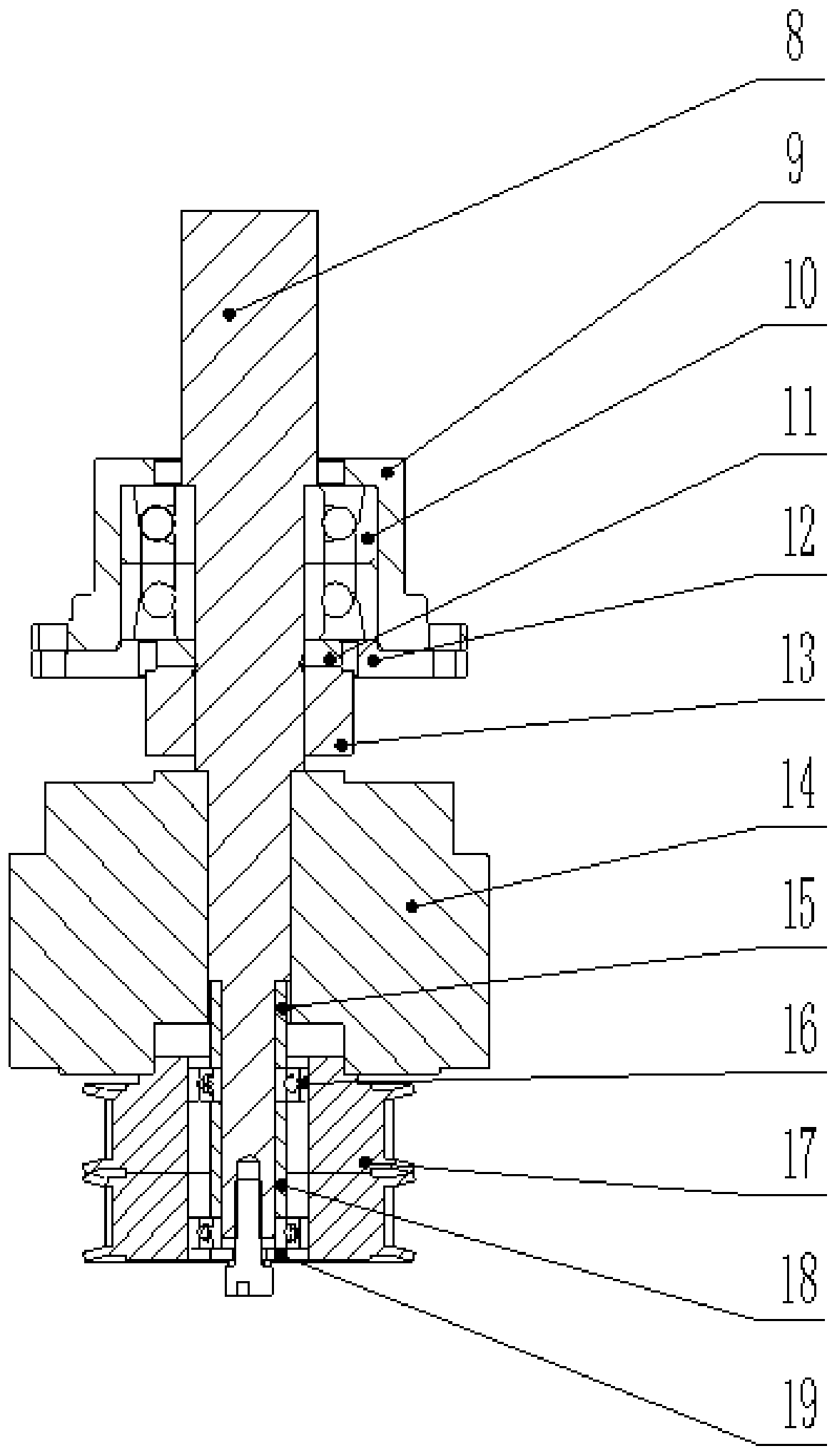
[0019] Such as Figure 1-Figure 5 As shown, this specific embodiment adopts the following technical solutions: it includes an underframe 1, a transmission support 2, a power output unit 3, a synchronous belt 4, a tensioner 5, a motor 6, a reducer 7, a rotating shaft 8, and a bearing cover 9 , angular contact ball bearing 10, nut bushing 11, handle base 12, belly lock nut 13, clutch 14, clutch bushing 15, deep groove ball bearing 16, triple synchr...


PUM


Abstract

The invention discloses a flexible multi-point transmission device, and belongs to the technical field of transmission equipment. A transmission support is arranged on the upper part of a bottom frame; a power output unit is arranged on the transmission support; the power output unit and a connecting seat are connected to the transmission support through a bearing gland; an angular contact ball bearing is assembled back to back an inner hole of the bearing gland; a rotary shaft is assembled in an inner hole of the angular contact ball bearing; a shaft shoulder structure is arranged at the upper end of a contact part of the rotary shaft and the bearing; a screw thread structure is arranged at the lower end of the contact part of the rotary shaft and the bearing; a clutch is arranged at thelower end of the rotary shaft; a triple synchronous pulley is positioned at the lower end of a rotor of the clutch through a seam allowance structure; a control system adopts a one-to-more communication manner, and various groups of signals are collected to one-path output through using an or circuit, so that the power output of an executing mechanism is controlled; and the flexible multi-point transmission device adopts flexible multi-point transmission, so that one power source drives multiple executing mechanisms, the synchronous movement, the partial linkage and the independent movement ofthe executing mechanisms are realized, and the working efficiency of the equipment is improved.

Description

technical field [0001] The invention relates to a flexible multi-point transmission device, which belongs to the technical field of transmission equipment. Background technique [0002] As a pillar industry of our country, the manufacturing industry has always maintained a good development trend. Emerging technologies are constantly being applied in production practice. On the premise of realizing their basic functions, the manufactured equipment is gradually becoming intelligent, informatized, serialized, and efficient. At the same time, the support device for workpiece processing is required to be fast, convenient and safe, and it is also strict for the transmission device; the change of the support device takes up a lot of non-processing man-hours, which affects the improvement of enterprise productivity. Most of the existing equipment adopts the method of replacing the supporting device to realize the production change, and each actuator is equipped with a power source f...

Claims


Application Information

Patent Timeline
IPC IPC(8): F16H57/021F16H57/023F16H7/02F16H7/08
CPCF16H57/021F16H57/023F16H7/02F16H7/08
Inventor 李怀志李国峰严海纲王策何涛毕雅夫
Owner 无锡恒久安泰智能制造有限公司
Why Eureka
Try Eureka