
Efficient cutting device for plate machining

A cutting device and plate processing technology, applied in metal processing equipment, metal processing machine parts, manufacturing tools, etc., can solve the problems of limited plate thickness range and inability to adapt to plate cutting of various thicknesses, and achieve wide application range and cutting work flexible effects

Inactive Publication Date: 2019-08-20
HEFEI YAKELI NEW BUILDING MATERIAL CO LTD
View PDF7 Cites 2 Cited by
  • Summary
  • Abstract
  • Description
  • Claims
  • Application Information

AI Technical Summary

Problems solved by technology

However, the range of sheet thickness that can be cut is limited, and it cannot adapt to the cutting of sheets of various thicknesses.

Method used


Image

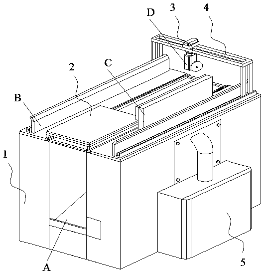
  • Efficient cutting device for plate machining
  • Efficient cutting device for plate machining
  • Efficient cutting device for plate machining

Examples


Embodiment Construction

[0041] Below in conjunction with specific embodiment, further illustrate the present invention. These examples are only for illustrating the present invention and are not intended to limit the scope of the present invention. In the description of the present invention, it should be noted that unless otherwise specified and limited, the terms "installation", "installation" and "connection" should be interpreted in a broad sense, for example, it can be a fixed connection or an optional connection. Detachable connection, or integral connection; it can be mechanical connection or electrical connection; it can be direct connection or indirect connection through an intermediary, and it can be the internal communication of two components. Those of ordinary skill in the art can understand the specific meanings of the above terms in the present invention in specific situations.

[0042] Now in conjunction with the accompanying drawings, the structural features of the present invention...


PUM


Abstract

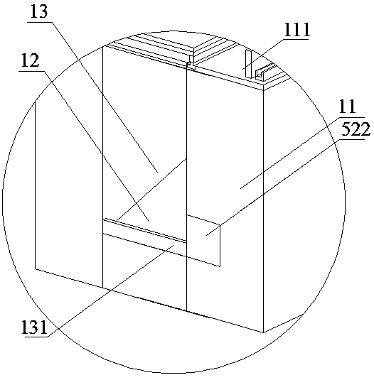
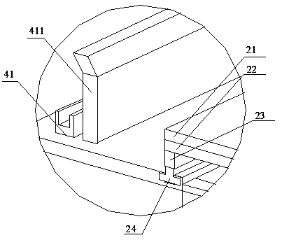
The invention discloses an efficient cutting device for plate machining. The device comprises a support mechanism and a plate conveying platform; a cutting mechanism is arranged above the plate conveying platform; the support device comprises a pair of support surfaces, and a waste collecting tank embedded between the support surfaces; the plate conveying platform comprises a conveying panel, anda lifting panel arranged on the conveying panel; an extension shaft is arranged in the center of the conveying panel; an output end of the extension shaft is connected to the bottom surface of the lifting panel; the lifting panel can be horizontally ascended and descended; and a powder recovery mechanism is arranged on the outer side of the support mechanism. Through arrangement of the lifting panel, the device can be suitable for cutting of plates with multiple thicknesses; and in addition, the cutting mechanism can be transversely and longitudinally operated, so that the cutting work is moreflexible, and the application range is wider.

Description

technical field [0001] The invention belongs to the technical field of workpiece processing equipment, and in particular relates to a high-efficiency cutting device for plate processing. Background technique [0002] Existing cutting equipment mainly includes a machine platform for placing the plate to be cut, a positioning block group and a cutting mechanism arranged on the machine platform for positioning the plate to be cut, because in the existing cutting equipment, the positioning block group and the cutting mechanism The positions are all fixed relative to the machine table and are inconvenient to adjust, resulting in that only boards of predetermined size can be cut, and the applicability is poor. In addition, the existing cutting equipment is quite bulky, takes up a lot of space, and is not easy to move. [0003] The Chinese utility model patent with the notification number CN205928769U discloses a plate cutting device for cutting masks or mask raw material plates, ...

Claims


Application Information

Patent Timeline
IPC IPC(8): B23D79/00B23Q11/00
CPCB23D79/00B23Q11/0046
Inventor 曹克莉曹克红戴芹汝岳佐霞
Owner HEFEI YAKELI NEW BUILDING MATERIAL CO LTD
Learn More