
Pyrolysis stirring apparatus for treating contaminated soil

A technology of polluted soil and stirring device, which is applied in the field of stirring device, can solve the problems affecting the quality of soil treatment, uneven heating of soil, incomplete pyrolysis, etc., to improve the efficiency and quality of pyrolysis, and the soil is fully heated and heated Effect

Inactive Publication Date: 2019-08-20
HUNAN CITY UNIV
View PDF12 Cites 3 Cited by
  • Summary
  • Abstract
  • Description
  • Claims
  • Application Information

AI Technical Summary

Problems solved by technology

However, when the existing pyrolysis stirring device is used to pyrolyze the soil, the soil is accumulated in the equipment, and the stirring is uneven and insufficient, resulting in uneven heating of the soil and incomplete pyrolysis, which affects the quality of soil treatment.

Method used


Image

  • Pyrolysis stirring apparatus for treating contaminated soil
  • Pyrolysis stirring apparatus for treating contaminated soil
  • Pyrolysis stirring apparatus for treating contaminated soil

Examples


Embodiment 1

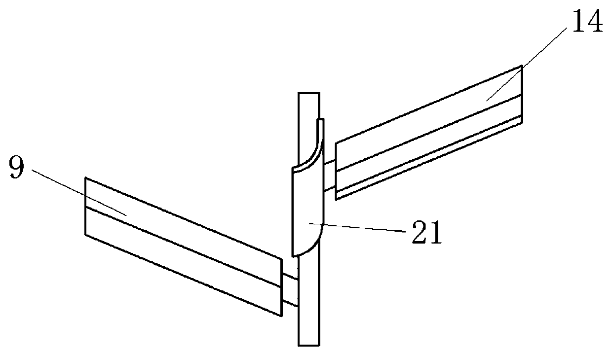
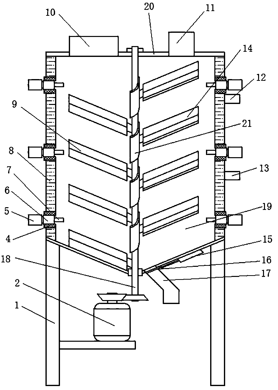
[0025] Such as Figure 1-2 As shown, a pyrolysis tank 19 is welded on the frame 1, and a top cover 20 is connected by bolts on the top of the pyrolysis tank 19, and a feed inlet 10 and an exhaust port 11 are welded on the top cover 20. A jacket 8 is arranged on the outside of the side wall of the pyrolysis tank 19, an oil inlet 13 and an oil outlet 12 are arranged on the jacket 8, and a group of ultrasonic vibration components are arranged on the side wall of the pyrolysis tank 19. The heat insulation bushing 4 that is threaded on the side wall of the pyrolysis tank 19 and runs through the side wall is threaded on the heat insulation bush 4 and the ultrasonic horn 6 and the tool head 7 fixed at one end of the ultrasonic horn 6, An ultrasonic transducer 5 is fixed at the other end of the ultrasonic horn 6 , the tool head 7 is located inside the pyrolysis tank 19 , and the ultrasonic transducer 5 is located outside the pyrolysis tank 19 .

[0026] The bottom of the pyrolysis ta...

Embodiment 2

[0029] Such as Figure 2-3 Shown, different from embodiment 1 is:

[0030] Three groups of ultrasonic vibration components are arranged on the side wall of the pyrolysis tank 19 .

[0031] Other content is identical with embodiment 1.

[0032] The working principle of the present invention is: heat the heat-conducting oil to the set temperature by the external heat-conducting oil furnace, pass the heat-conducting oil into the jacket 8 from the oil inlet 13, and flow back into the heat-conducting oil furnace from the oil outlet 12. Open the external ultrasonic generator through external control, open the stirring motor 2, and the cylinder 15 is connected to the external air source and stretched out, so that the material blocking plate 16 closes the discharge pipe 17. The polluted soil is sent into the pyrolysis tank 19 from the feed inlet 10, and the polluted soil is constantly stirred in the thermal pyrolysis pipe 19, due to the first stirring paddle 9, the second stirring p...


PUM


Abstract

The invention discloses a pyrolysis stirring apparatus for treating the contaminated soil. The apparatus comprises a machine frame and a pyrolysis tank welded on the machine frame, wherein the top ofthe pyrolysis tank is connected with a top cover by bolts, the top cover is provided with a material inlet and a gas discharge port, a jacket is disposed at the outer side of the side wall of the pyrolysis tank, the jacket is provided with an oil inlet and an oil outlet, the side wall of the pyrolysis tank is provided with at least one set of ultrasonic vibration components, the bottom of the pyrolysis tank has a funnel shape, a stirring component is arranged at the center of the bottom of the pyrolysis tank, and a material discharge component is further arranged at the bottom of the pyrolysistank. The apparatus can fully stir the soil to ensure that the soil can be uniformly heated.

Description

technical field [0001] The invention relates to a stirring device, in particular to a pyrolysis stirring device for treating polluted soil. Background technique [0002] With the development of industrial production and the acceleration of urbanization, the soil bears more and more waste water, waste residue and waste gas from factories and human activities. If these wastes are not treated in a timely and effective manner, they will infiltrate into the soil along with the rainwater. When these pollutants accumulate to a level that exceeds the self-purification capacity of the soil, it will cause serious deterioration of the soil quality and form soil pollution. Soil remediation methods include thermodynamic remediation technology, thermal desorption remediation technology, incineration method, landfill method, chemical leaching method, composting method, phytoremediation method, infiltration reaction wall method and bioremediation method. [0003] Thermal desorption technol...

Claims


Application Information

Patent Timeline
Patent Type & Authority Applications(China)
IPC IPC(8): B09C1/06
CPCB09C1/065
Inventor 刘玉振
Owner HUNAN CITY UNIV
Learn More