
Stone Basket Disposal Appliance

A technology for disposing of instruments and basket lines, which is applied in the fields of medical science, surgery, diagnosis, etc., can solve the problems of inability to maintain and pull out the stone extraction basket from the pipeline, etc., and achieve the effect of easy removal.

Active Publication Date: 2021-11-02
OLYMPUS CORP
View PDF10 Cites 0 Cited by
  • Summary
  • Abstract
  • Description
  • Claims
  • Application Information

AI Technical Summary

Problems solved by technology

Since the stone extraction basket type gripping pliers have a structure to hold foreign objects with multiple wires, when recovering large foreign objects, sometimes the stone extraction basket cannot be pulled out from the pipeline without holding the foreign objects.
For example, in the stone-taking basket-type gripping pliers described in Patent Document 1, if the foreign matter does not escape from between the multiple wires, the stone-taking basket cannot be pulled out from the pipeline.

Method used


Image

  • Stone Basket Disposal Appliance
  • Stone Basket Disposal Appliance
  • Stone Basket Disposal Appliance

Examples


Deformed example 1

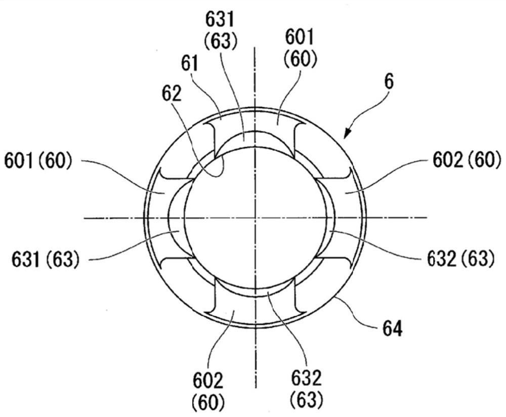
[0067] Modifications of the tip cover of the above-described embodiment will be described. Figure 9 It is a schematic diagram which shows the structure of the modification 1 of the said embodiment. In this variant, as Figure 9 As shown, the first surface 631A of the tip cover 6A is an R-angled surface, the second surface 632A is a C-angled surface, and the inclination angle and the amount of chamfering are the same. In this modification, when the stone basket wire 2 contacts the corner formed at the boundary between the second surface 632A and the bottom 61 or the corner formed at the boundary between the second surface 632A and the inner peripheral surface 62, the Stress tends to concentrate at this contact location. On the other hand, since the first surface 631A is an R-angled surface and no corner such as the second surface 632A is formed, it is less likely to be broken than the basket wire 2 passing through the second groove 602 . In this way, even if the amount of c...

Deformed example 2

[0069] Figure 10 It is a schematic diagram which shows the structure of the modification 2 of the tip cover of the said embodiment. The inclined surface of the top end cover is not limited to the R angle surface and the C angle surface, but can also be as Figure 10 Shown is the inclined surface 63B in which the C-angle surfaces with slightly different inclination angles are continuously formed. exist Figure 10 In the shown modification, the length m2 of the 1st surface 631B and the 2nd surface 632B differs. In this modification, the length m22 of the second surface 632B is shorter than the length m21 of the first surface 631B. Therefore, when tension is applied to the stone extraction basket wire 2, the stone extraction basket wire 2 passing through the second groove 602 is acted with a larger breaking force than the stone extraction basket wire 2 passing through the first groove 601, which is different from that of the stone extraction basket wire 2 passing through the ...


PUM


Abstract

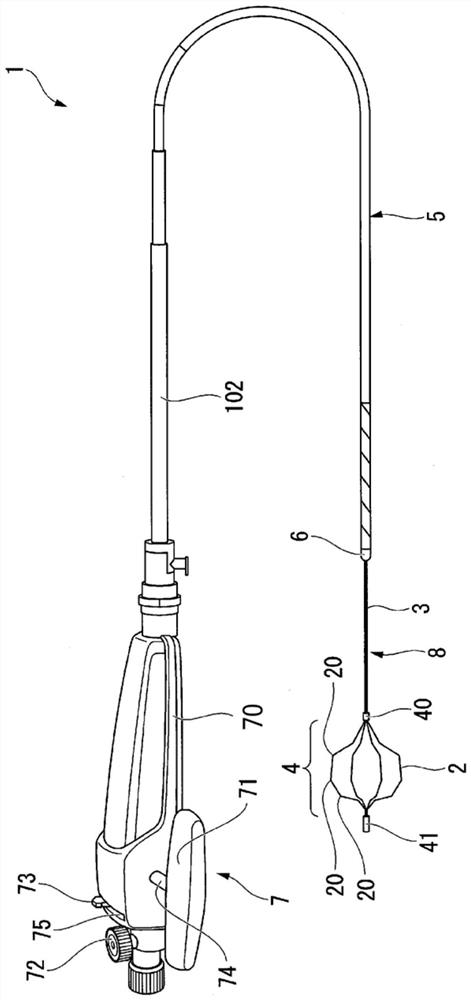
The stone extraction basket type treatment instrument of the present invention includes a sheath, a top end cover installed on the top of the sheath and having a plurality of grooves, a plurality of stone retrieval basket wires and an operation wire forming the stone extraction basket, and the plurality of grooves have a first A groove and a second groove, the first groove has a first surface inclined from the bottom surface of the first groove toward the inner peripheral surface of the tip cover, the first surface is passed through the first In the bottom surface of the groove, at least the inner peripheral surface side of the tip cover is chamfered, and the second groove has a second surface from the bottom surface of the second groove toward the tip cover. The inner peripheral surface is inclined, and the second surface is formed by chamfering at least the inner peripheral surface side of the tip cover in the bottom surface of the second groove into a shape different from that of the first surface, and the When the operation wire is pulled with the object to be disposed in the stone retrieval basket, the plurality of stone retrieval basket wires are pulled so as to pass through the plurality of different grooves respectively, and the breaking force of the stone retrieval basket wires is The first side and the second side are different.

Description

technical field [0001] The invention relates to a stone basket-type disposal device. Background technique [0002] Conventionally, there has been known a basket-type grasping forceps for collecting stones, etc., which are inserted into a conduit such as a bile duct in the body (for example, refer to Patent Document 1). Since the stone basket-type grasping forceps have a structure in which foreign matter is held by a plurality of wires, when collecting a large foreign matter, the stone basket may not be pulled out from the pipeline without holding the foreign matter. For example, in the stone basket type grasping forceps described in Patent Document 1, the stone basket cannot be pulled out from the pipeline unless the foreign matter is detached from the plurality of wires. [0003] prior art literature [0004] Patent Literature [0005] Patent Document 1: Japanese Patent Laid-Open No. 2013-22386 SUMMARY OF THE INVENTION [0006] Invention to solve problem [0007...

Claims


Application Information

Patent Timeline
Patent Type & Authority Patents(China)
IPC IPC(8): A61B17/221
CPCA61B17/221A61B2090/037A61B2017/2212A61B2017/00336A61B2017/00818
Inventor 岩崎畅喜
Owner OLYMPUS CORP
Learn More