
Circuit fusing protection method

A fusing and circuit technology, used in circuits, emergency protection devices, electrical components, etc., can solve problems such as damage to electrical appliances, danger, and easy occurrence of electric shock, and achieve the effect of improving safety performance, strong safety performance, and improving convenience.

Active Publication Date: 2019-08-16
江苏科兴电器有限公司
View PDF8 Cites 7 Cited by
  • Summary
  • Abstract
  • Description
  • Claims
  • Application Information

AI Technical Summary

Problems solved by technology

[0002] The fuse is one of the common circuit protection components in daily life. It is mainly used for overload protection. It is often connected in series with the live line of the circuit. If the fuse is correctly placed on the incoming line of the live wire, the fuse will be activated when the current abnormally rises to a certain height and heat. , self-fusing and cutting off the live wire, so as to realize the protection function of the electrical equipment and the circuit. The fuse is a very effective, safe and reliable circuit protector, but there are certain inconveniences in the use of the fuse. After the fuse is blown due to overload, the user needs to manually replace the fuse. Since the fuse is connected in series to the live line, there is a certain risk of replacing the fuse, and it is very easy to cause the risk of electric shock. Therefore, the present invention Man designed a rotating self-replacement circuit fusing protection method with ingenious structure, simple principle, automatic replacement after fusing, and strong safety performance.

Method used


Image

  • Circuit fusing protection method
  • Circuit fusing protection method
  • Circuit fusing protection method

Examples


Embodiment Construction

[0049] A circuit fusing protection method, the steps of which are:

[0050] (1) The normal operation stage of the circuit;

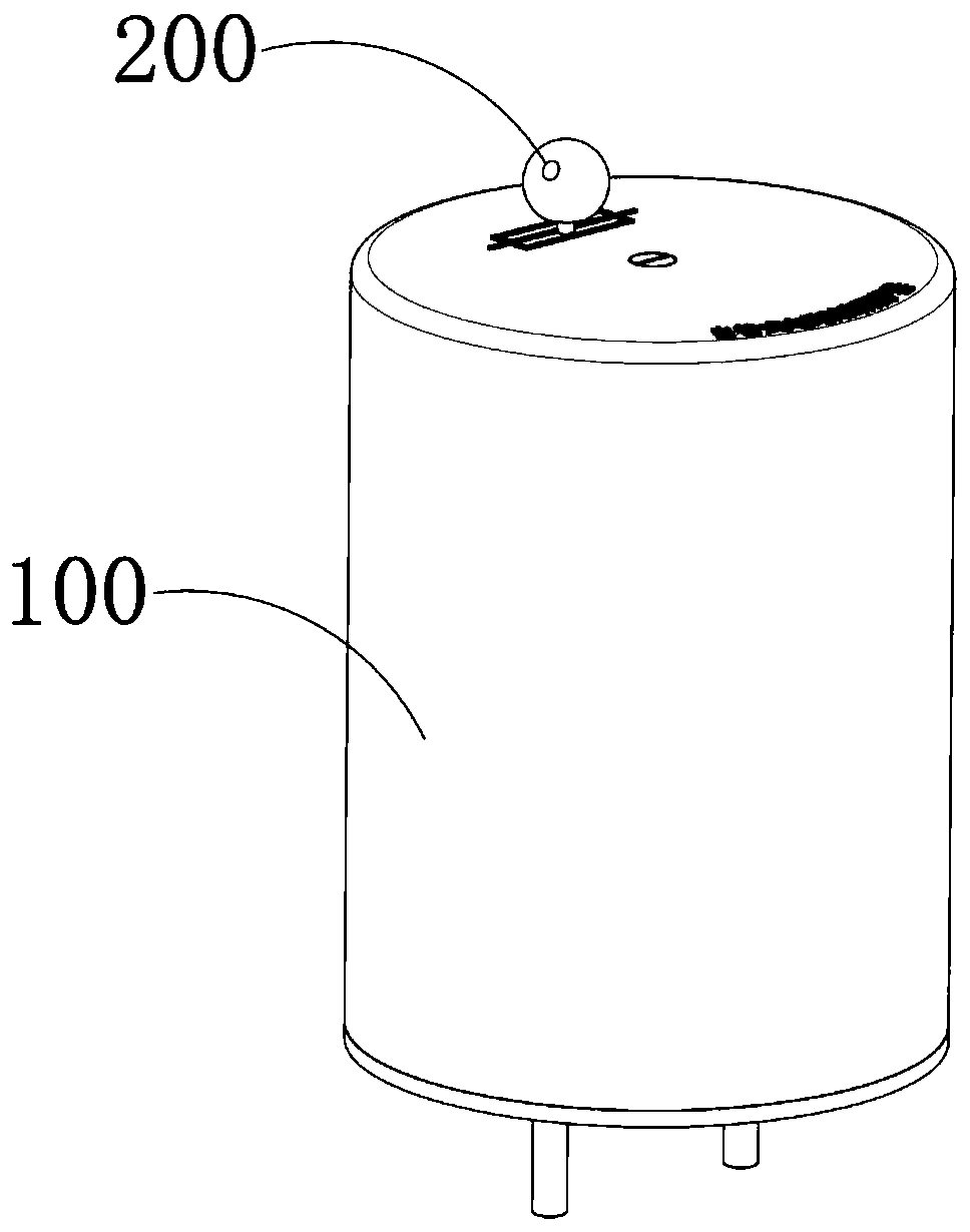
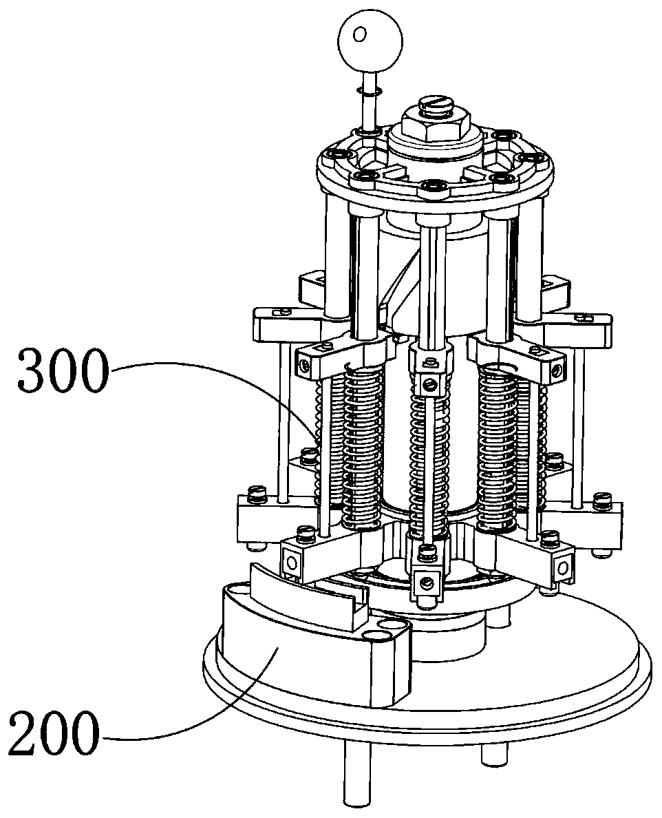
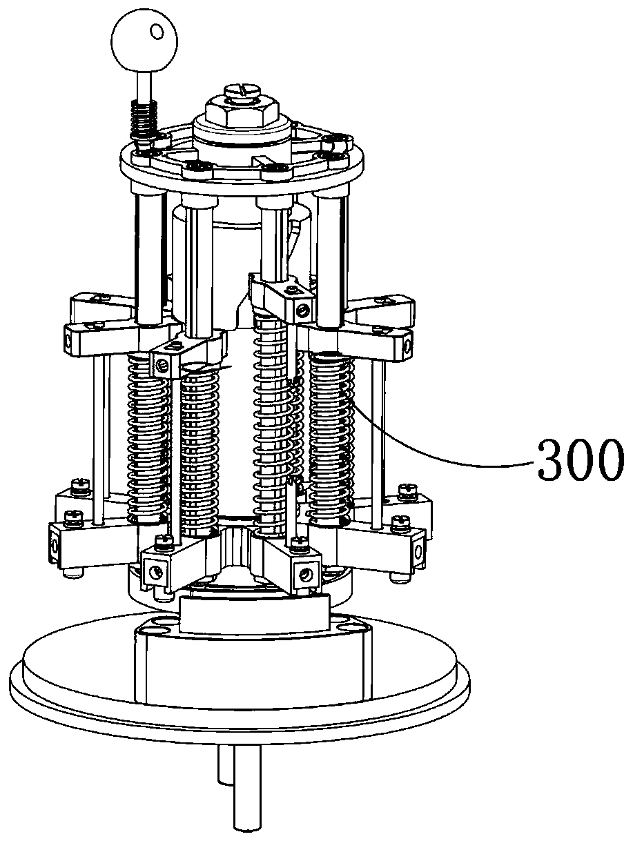
[0051] S1: The user connects the wiring member 200 to the live wire in series, the fuse rotating mechanism 300 connects the disconnected wiring member 200, and the circuit is in normal operation;

[0052] The wiring member 200 includes a fixing column 201 fixedly installed between the insulating base plate 110 and the closed end of the insulating shell 120. The fixing column 201 is coaxially arranged with the insulating base plate 110, and the fixing column 201 is coaxially fixed and sleeved with a conductive plate 202. , the conductive plate 202 is arranged close to the insulating bottom plate 110 , and one end face of the conductive plate 202 away from the insulating bottom plate 110 is coaxially provided with an annular chute 203 . One end face is fixedly provided with a terminal one 204, and the terminal one 204 is movable through the insulating bas...


PUM


Abstract

The invention provides a circuit fusing protection method, which includes the steps are as follows: firstly, a user connects a wiring component in series to a live line, a fusing rotation mechanism connects the disconnected wiring component, and the circuit is in normal operation; secondly, when fault current overload occurs in the circuit and causes the temperature of a conductive fuse wire to rise to a certain value, the conductive fuse wire fuses automatically, and the fusing rotation mechanism automatically cuts off the connection between a conductive disc and a conductive block; thirdly,after the fault of the circuit is eliminated, the rotation restriction of a limit mechanism on the fusing rotation mechanism is relieved by manual pulling; and finally, the elastic potential energy inside the fusing rotation mechanism is triggered to be released and fuse wires arranged in an array are rotated to separate the fused fuse wire from the wiring component, a new fuse wire is switched toa conducive fuse wire, the fusing rotation mechanism restores the conduction of the wiring component, and the circuit is restored to the normal operation stage.

Description

technical field [0001] The invention relates to a circuit protector, in particular to a circuit fusing protection method. Background technique [0002] The fuse is one of the common circuit protection components in daily life. It mainly plays the role of overload protection. It is often connected in series with the live wire of the circuit. When the circuit is overloaded, the circuit will be overloaded, and the circuit will be damaged, and the electrical equipment will be damaged. The fuse is a very effective, safe and reliable circuit protector, but the fuse also has certain inconveniences in the use process, when the circuit current After overloading and causing the fuse to blow, the user needs to manually replace the fuse. Since the fuse is connected in series with the live wire, there is a certain danger in replacing the fuse, and the risk of electric shock is very likely to occur. For this reason, the present invention People have designed a rotary self-replacement ci...

Claims


Application Information

Patent Timeline
Patent Type & Authority Applications(China)
IPC IPC(8): H01H85/22H01H85/20
CPCH01H85/205H01H85/22
Inventor 张家霞
Owner 江苏科兴电器有限公司
Learn More