Array element position calibration measurement point interval optimization method of hydroacoustic positioning and navigation system

An array element location and navigation system technology, applied in radio wave measurement systems, instruments, etc., can solve the problems of small calculation amount, large model mismatch error, ignoring model mismatch problems, etc., to eliminate model mismatch errors and improve Effects of Calibration Accuracy

Active Publication Date: 2019-08-16
HARBIN ENG UNIV
View PDF9 Cites 1 Cited by
  • Summary
  • Abstract
  • Description
  • Claims
  • Application Information

AI Technical Summary

Problems solved by technology

In the traditional absolute calibration process, the general survey ship sails in a circular track centered around the point where the array element to be measured is placed, during which it conducts uninterrupted inquiry and response with the array element at a fixed period, and records the position information of the survey ship and the query-response time. Extend the information, and then select the relevant information on the three measurement points that are equilateral triangles to use the spherical intersection model to solve. When the depth of the array element to be measured is known, the spherical intersection model degenerates into a circular intersection model. The model of this method is simple. The amount of calculation is small, but the model mismatch problem caused by the different receiving and transmitting positions caused by the movement of the measuring ship is ignored. The faster the moving speed of the measuring ship, the greater the model mismatch error and the lower the accuracy of array element position calibration
Moreover, the optimal selection of the measurement point spacing is not considered in the measurement process, which in turn affects the calibration accuracy and calibration efficiency of the array element position

Method used


Image

  • Array element position calibration measurement point interval optimization method of hydroacoustic positioning and navigation system
  • Array element position calibration measurement point interval optimization method of hydroacoustic positioning and navigation system
  • Array element position calibration measurement point interval optimization method of hydroacoustic positioning and navigation system

Examples


specific Embodiment 1

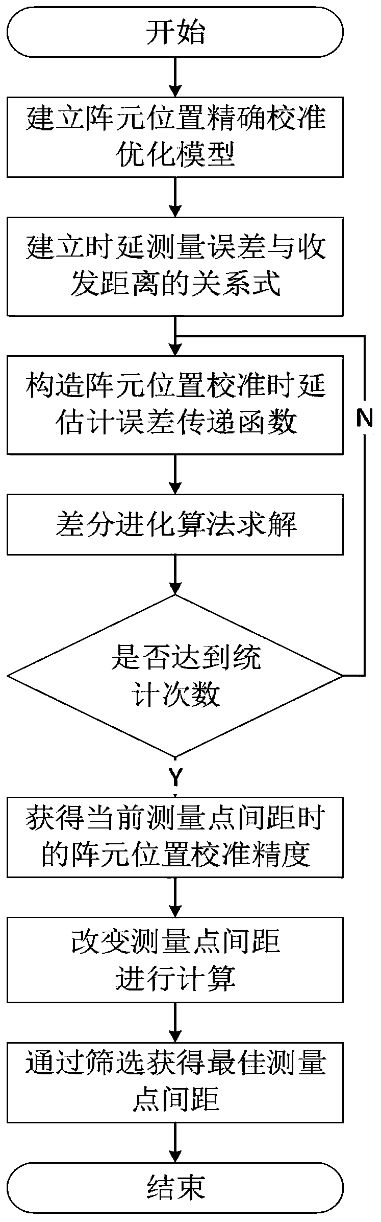
[0044] The present invention provides a method for optimizing the distance between array element position calibration and measurement points of an underwater acoustic positioning navigation system. The method includes the following steps:

[0045] Step 1: According to the measurement position coordinates of the survey ship, establish an optimization model for accurate calibration of the array element position;

[0046] Step 2: Establish the relationship between the time delay measurement error and the sending and receiving distance function;

[0047] Step 3: Construct the error transfer function of the array element position calibration delay measurement, and use the differential evolution algorithm to solve the element position calibration delay measurement error transfer function to obtain the position result and error of the array element to be measured;

[0048] Step 4: Use statistical methods to obtain the calibration accuracy of the array element position;

[0049] Step...

specific Embodiment 2

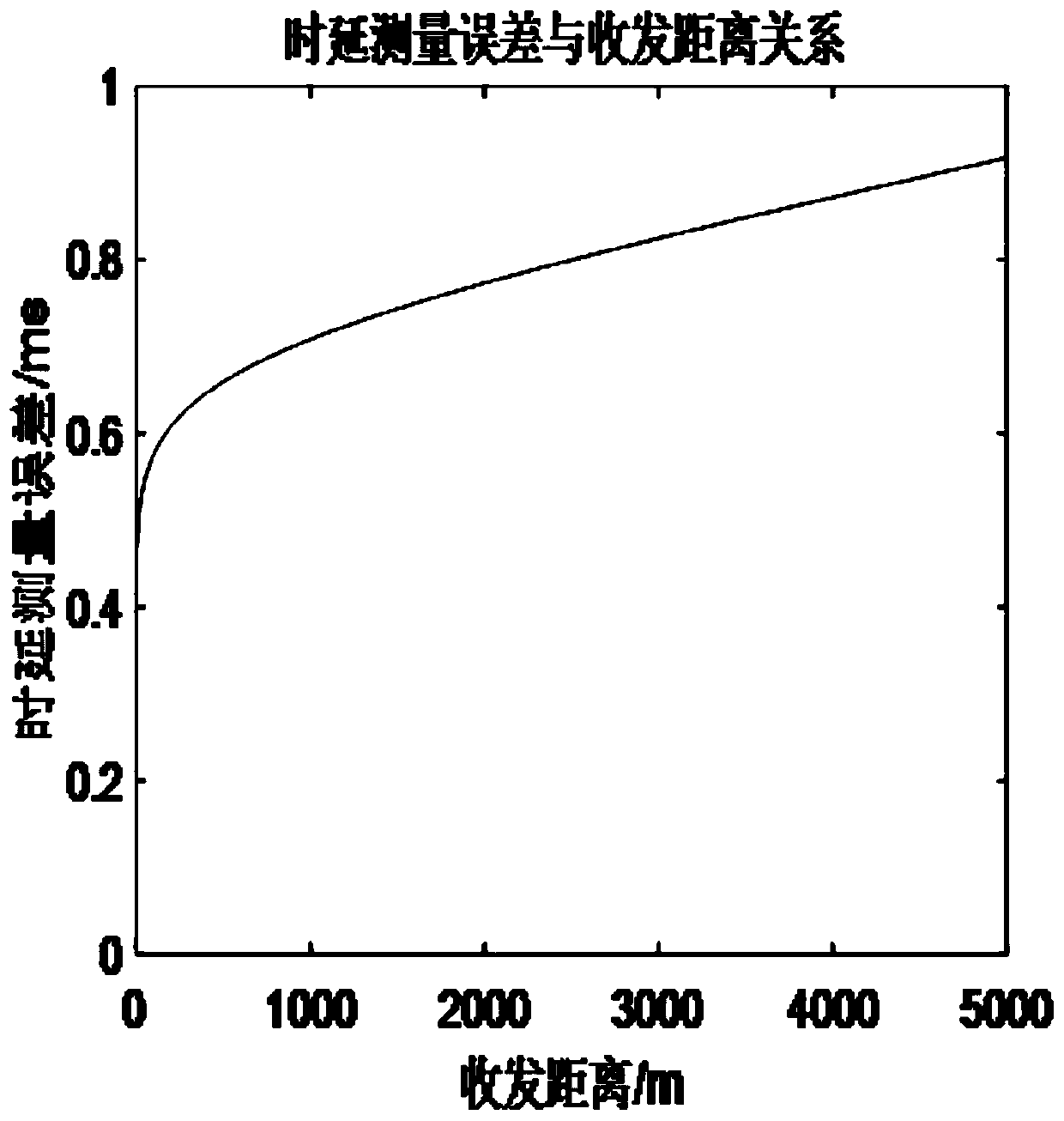
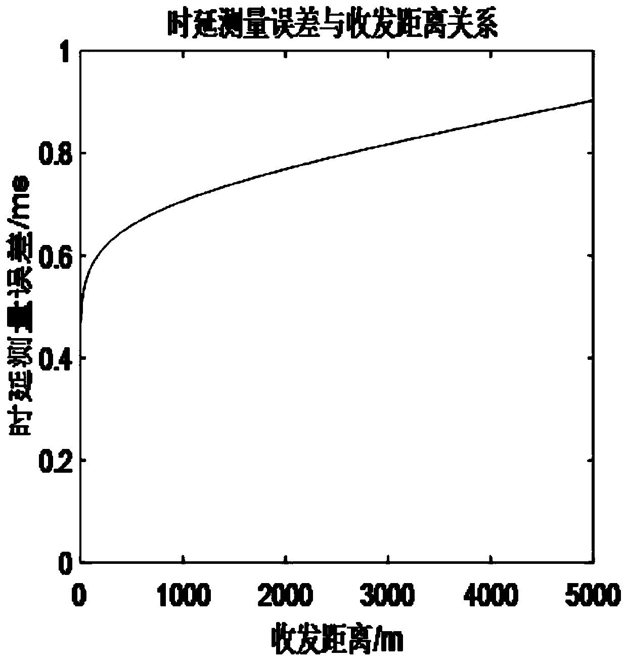
[0073] Firstly, the relationship between the delay measurement error of 10.5kHz and 11.5kHz signals and the distance between sending and receiving is given, as shown in figure 2 and image 3 shown. It can be seen from the figure that the delay measurement error increases with the increase of the transmitting and receiving distance, and the signal delay measurement error increases rapidly with the increase of the transmitting and receiving distance in the first 2000m, and then the growth trend tends to be flat.

[0074] Then the parameters are given as follows: the sound source of the measuring ship enters the water 6m, the moving speed of the measuring ship is 8m / s, the frequency of the interrogation sound signal is 10.5kHz, the distance between the measuring points is L, and the coordinates of the measuring points are respectively The position of the array element to be tested is The response signal frequency is 11.5kHz; the delay measurement error is related to the send...


PUM


Abstract

The invention discloses an array element position calibration measurement point interval optimization method of a hydroacoustic positioning and navigation system. In the method provided by the invention, an array element position accurate calibration optimization model, a relational expression of time delay measurement error and sending and receiving distance and an array element position calibration time delay estimation error transfer function are established; a differential evolution algorithm is used for solving, and to-be-measured array element position estimation results and errors are obtained. Array element position calibration accuracy is obtained through a statistical method; and an optimal measurement point interval is obtained through screening of all the results. With the method provided by the invention, model mismatch errors caused by surveying vessel movement are eliminated; the relational expression of time delay measurement error and sending and receiving distance isestablished, change of the measurement time delay error with change of the sending and receiving distance is considered, and relative to the conventional method of using fixed time delay measurement error, error analysis of the method is consistent with reality better. By array element position calibration measurement point interval optimization of the hydroacoustic positioning and navigation system, the optimal measurement point interval is obtained, and further improvement of calibration accuracy of the array element position is facilitated.

Description

technical field [0001] The invention relates to the technical field of underwater acoustic positioning, and relates to an optimization method for calibrating and measuring point spacing of an array element position of an underwater acoustic positioning navigation system. Background technique [0002] Since sound waves are the most effective carrier for underwater information transmission, and underwater acoustic positioning and navigation technology has the advantages of taking into account deep and shallow seas, all-weather, real-time, high reliability, and error does not accumulate over time, so underwater acoustic positioning and navigation technology has the advantages of underwater positioning technology. occupies an important position. [0003] The underwater array element is the star station node of the underwater acoustic positioning and navigation system, and its calibration accuracy is directly related to the working performance of the underwater acoustic positioni...

Claims


Application Information

Patent Timeline
IPC IPC(8): G01S7/52
CPCG01S7/52004
Inventor 付进张光普齐滨梁国龙王燕邹男翟笃文熊逸文孙思博王晋晋杨卓
Owner HARBIN ENG UNIV
Why Eureka
Try Eureka