Illuminating device and display device
A technology for lighting devices and light sources, which is applied in lighting devices, cooling/heating devices for lighting devices, lighting and heating equipment, etc., and can solve problems such as impossibility
- Summary
- Abstract
- Description
- Claims
- Application Information
AI Technical Summary
Problems solved by technology
Method used
Image
Examples
no. 1 approach
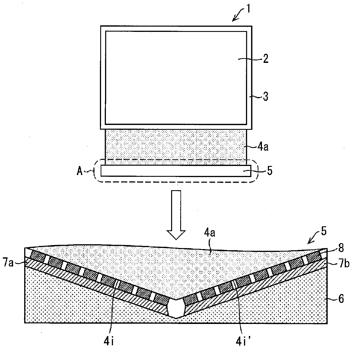
[0055] figure 1 It is a figure which shows the schematic structure of the illuminating device of 1st Embodiment.
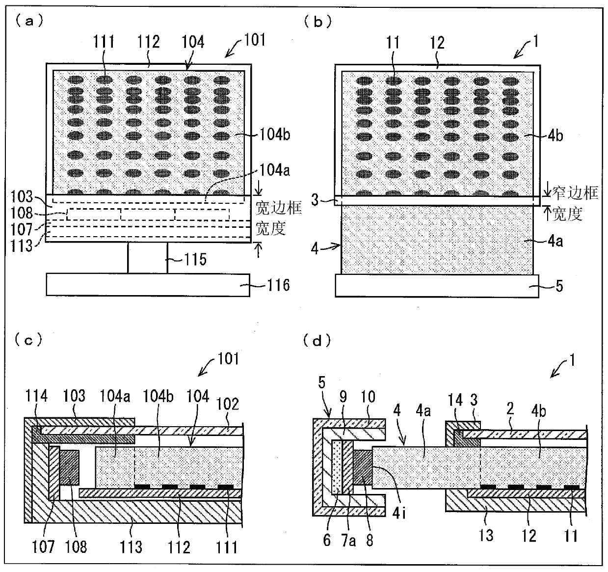
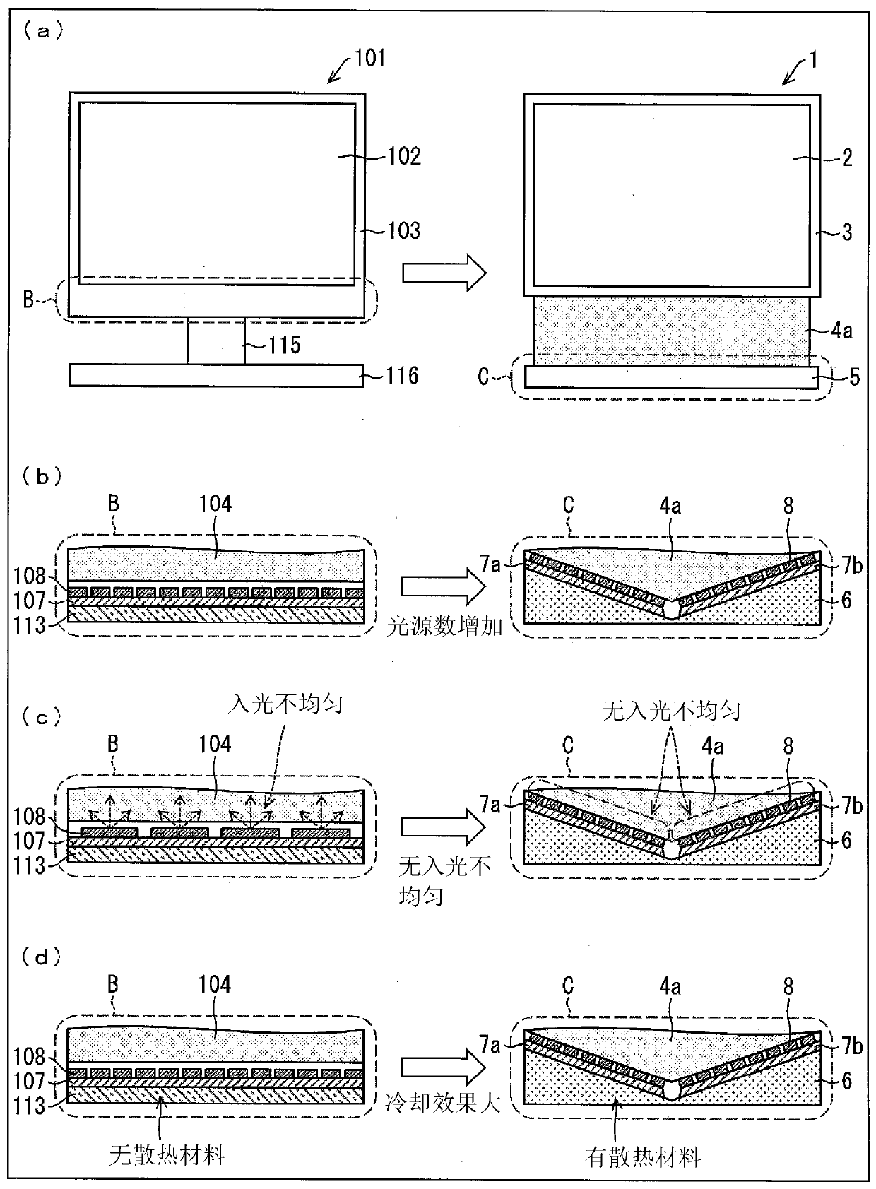
[0056] Such as figure 1 As shown, the lighting device 1 has a protective cover 2, a frame (outer frame) 3 covering the end of the protective cover 2, a light guide plate including incident surfaces 4i, 4i' and a light guide region 4a, and a support portion 5.
[0057] In the figure, as shown in the enlarged view of the area A indicated by the dotted line, the light guide plate has incident surfaces 4i, 4i' for allowing light from the light source 8 to enter the light guide plate, and light incident from the incident surfaces 4i, 4i'. The light is sufficiently diffused and guided to the light guide area 4a in the output area (not shown), and the output area (not shown) from which the light from the light guide area 4a is output.
[0058] Since the light guide plate including the incident surfaces 4i, 4i' and the light guide area 4a is supported by the support p...
no. 2 approach
[0103] Next, according to Figure 6 as well as Figure 7 , to describe the second embodiment of the present invention. This embodiment differs from the first embodiment in that a plurality of light sources 8 are arranged in a curved shape inside the support portion 5c, and other points are the same as those described in the first embodiment. For convenience of description, components having the same functions as those shown in the drawings of the first embodiment are given the same reference numerals, and description thereof will be omitted.
[0104] Figure 6 It is a figure which shows the schematic structure of the lighting apparatus 1a.
[0105] Such as Figure 6 As shown, the lighting device 1a has a protective cover 2, a frame (outer frame) 3 covering the end of the protective cover 2, a light guide plate including incident surfaces 4i, 4c and a light guide region 4a, and a support portion 5c.
[0106] As illustrated in the enlarged view of a region D indicated by a ...
no. 3 approach
[0126] Next, according to Figure 8 as well as Figure 9 , the third embodiment of the present invention will be described. In this embodiment, the difference from the first and second embodiments is that a light source unit is arranged as a light source 18 in the support portion 5f, and each light source unit is composed of a red light emitting diode 8R, a green light emitting diode 8G, The configuration in which the blue light emitting diodes 8B are arranged adjacent to each other is the same as that described in the first embodiment and the second embodiment. For convenience of description, components having the same functions as those shown in the drawings of the first embodiment and the second embodiment are given the same reference numerals, and description thereof will be omitted.
[0127] Figure 8 It is a diagram showing a schematic configuration of the lighting device 1b. The lighting device 1b has a light source unit as a light source 18 in the support portion 5f...
PUM
 Abstract
Description
Claims
Application Information
 - Generate Ideas
- Intellectual Property
- Life Sciences
- Materials
- Tech Scout
- Unparalleled Data Quality
- Higher Quality Content
- 60% Fewer Hallucinations
Browse by: Latest US Patents, China's latest patents, Technical Efficacy Thesaurus, Application Domain, Technology Topic, Popular Technical Reports.
© 2025 PatSnap. All rights reserved.Legal|Privacy policy|Modern Slavery Act Transparency Statement|Sitemap|About US| Contact US: help@patsnap.com


