seat air conditioner

A technology for air conditioners and seats, which is applied to vehicle seats, chairs, transportation and packaging, etc., can solve the problems of reduced air conditioning performance of seat air conditioners, rising temperature of inhaled air, inhaling dust, dust, etc.

Active Publication Date: 2022-03-15
DENSO CORP
View PDF6 Cites 0 Cited by
  • Summary
  • Abstract
  • Description
  • Claims
  • Application Information

AI Technical Summary

Problems solved by technology

In this case, the temperature of the intake air rises, and after being cooled by the refrigeration cycle, the temperature of the air blown out to the occupants also rises, resulting in a decrease in the cooling performance of the seat air conditioner.
[0011] And, in the case of this structure, when the air is s

Method used


Image

  • seat air conditioner
  • seat air conditioner
  • seat air conditioner

Examples


no. 1 approach

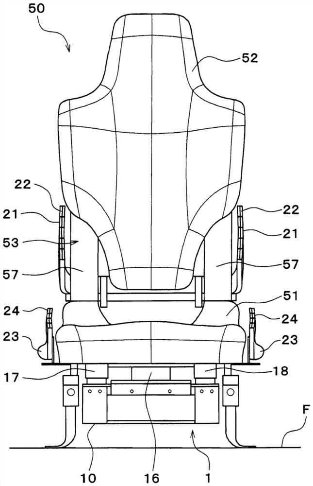
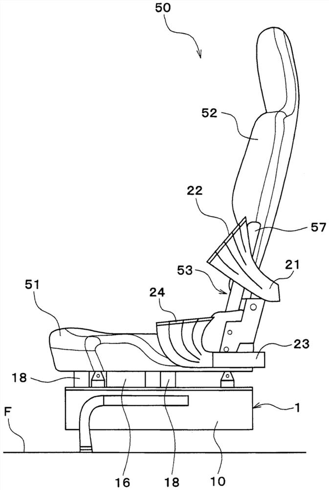
[0056] The seat air conditioner 1 of the first embodiment is applied to an air conditioner of an electric vehicle running on electric power of a battery. Such as figure 1 , figure 2 As shown, the seat air conditioner 1 is disposed in a small space between the seat surface 51 of the seat 50 of the electric vehicle and the floor surface F of the vehicle compartment, and improves the sitting condition by forming an air flow A of temperature-adjusted air. The comfort of the occupant in the seat 50.

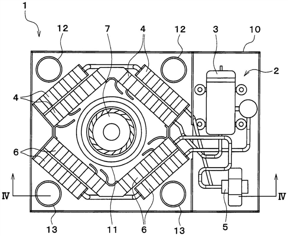
[0057] The seat air conditioner 1 is configured by accommodating a vapor compression refrigeration cycle 2 and a blower 7 inside a casing 10 . Therefore, the seat air conditioner 1 can adjust the temperature of the blown air generated by the operation of the blower 7 through the refrigeration cycle 2, and send air to the seat as air-conditioning air through the seat 50, the main duct 21, and the foot duct 23. 50 crew supplies.

[0058] In addition, the seat 50 has a seat portion ...

no. 2 approach

[0127] Next, a second embodiment different from the first embodiment described above will be described with reference to the drawings. The seat air conditioner 1 of the second embodiment is applied to an air conditioner of an electric vehicle running on electric power of a battery, as in the first embodiment. Next, in the following description, the same code|symbol as 1st Embodiment represents the same structure, and the previous description is referred.

[0128] Such as Figure 8 , Figure 9 As shown, the seat air conditioner 1 of the second embodiment is arranged in a small space between the seat surface 51 of the seat 50 of the electric vehicle and the floor surface F of the vehicle compartment similarly to the first embodiment. The air flow A of the seat 50 is used to improve the comfort of the occupant seated in the seat 50 .

[0129] Next, the seat air conditioner 1 accommodates a vapor compression refrigeration cycle 2 and a blower 7 using a centrifugal multi-blade f...


PUM


Abstract

The present invention relates to a seat air conditioner arranged below a seat portion of a seat, and an object of the present invention is to provide a seat air conditioner capable of suppressing a decrease in air conditioning performance associated with intake of air. A seat air conditioner includes a housing (10) disposed in a space formed below a seat surface (51) of a seat (50) in a vehicle interior and above a vehicle interior floor surface (F). . Inside the housing is provided: a compressor (3), which compresses and discharges refrigerant; a condenser (4), which makes the refrigerant discharged from the compressor heat dissipation; the decompression part (5), the decompression part (5) decompresses the refrigerant flowing out from the condenser; the evaporator (6), the evaporator (6) decompresses the refrigerant the compressed refrigerant evaporates; and a blower (7) that blows air to be heat-exchanged with the refrigerant. The air blower is capable of sucking in the air through a ventilation opening (11) formed on the upper surface of the casing.

Description

[0001] Cross-reference of related applications [0002] This application is based on Japanese Patent Application No. 2017-10520 for which it applied on January 24, 2017, and uses the description content here. technical field [0003] The present invention relates to a seat air conditioner for supplying conditioned air to a seat. Background technique [0004] Conventionally, various seat air conditioners have been developed in order to provide a comfortable temperature environment for occupants seated in the seats. [0005] The seat air conditioner described in Patent Document 1 is disposed between the seat surface and the floor of the seat, and includes a vapor compression refrigeration cycle inside the casing. The seat air conditioner improves the comfort of an occupant seated in the seat by blowing air-conditioned air whose temperature has been adjusted by a refrigeration cycle to the seat. [0006] prior art literature [0007] patent documents [0008] Patent Documen...

Claims


Application Information

Patent Timeline
IPC IPC(8): B60H1/00A47C7/74B60H1/32
CPCA47C7/74B60H1/00B60H1/32B60N2/5635B60N2/5657B60N2/5678
Inventor 川野茂
Owner DENSO CORP
Why Eureka
Try Eureka