A power factor correction circuit, method, charger and electric vehicle

A power factor correction and correction circuit technology, which is applied in the field of circuits, can solve problems such as excessively large inductors, and achieve the effects of improving excessively large inductors, improving utilization, and eliminating losses

Active Publication Date: 2021-03-30
QINGDAO UNIV
View PDF4 Cites 0 Cited by
  • Summary
  • Abstract
  • Description
  • Claims
  • Application Information

AI Technical Summary

Problems solved by technology

[0006] In order to solve the deficiencies of the prior art, the present disclosure provides a power factor correction circuit, method, charger and electric vehicle, using two rectifier tubes to replace the diode bridge arm in the existing pseudo-totem pole circuit and two diodes to perform synchronous rectification The role of one of the inductors is replaced by a coupling inductor with a small inductance at the opposite end, and the other inductor is used as the main inductor for energy transfer, thereby improving the utilization rate of the inductor and also improving the problem of the excessive volume of the inductor

Method used


Image

  • A power factor correction circuit, method, charger and electric vehicle
  • A power factor correction circuit, method, charger and electric vehicle
  • A power factor correction circuit, method, charger and electric vehicle

Examples


Embodiment 1

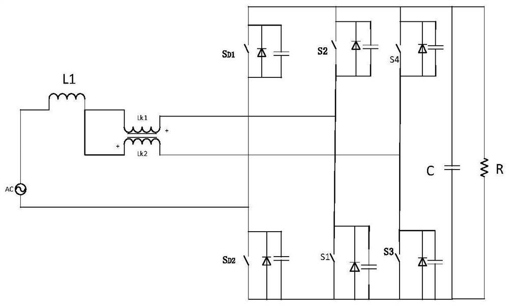
[0045] Such as image 3 As shown, Embodiment 1 of the present disclosure provides a power factor correction circuit, including an AC power supply AC, a first inductor L1, a first heteronymously coupled inductor, a first switch tube S 1 , the second switch tube S 2 , the third switch tube S 3 , the fourth switch tube S 4 , the first rectifier tube S D1 , the second rectifier tube S D2 , the first capacitor C and the first load R, the first coupled inductance includes the second inductance L K1 and the third inductance L K2 , the positive terminal of the AC power supply AC is connected to the first inductance L 1 connected with the second inductor L K1 connected to the first end of the third inductance LK2, the second inductance L K1 The second end of the second switch tube S is respectively connected to the 2 The first terminal and the first switching tube S 1 connected to the second end of the second switching tube S 2 The second end of the fourth switch tube S 4 T...

Embodiment 2

[0049] Embodiment 2 of the present disclosure provides a power factor correction method. Using the power factor correction circuit described in Embodiment 1 of the present disclosure, when the AC input is in the positive half cycle, the second rectifier tube S D2 conduction, the first switch tube S 1 and the third switching tube S 3 The phase difference is 180°, and the second switch tube S 2 and the fourth switching tube S 4 Working in the diode state, the first switching tube S 1 and the second switch tube S 2 Complementary conduction, the third switch tube S 3 and the fourth switching tube S 4 Complementary conduction to form the first interleaved parallel Boost converter, such as Figure 4 shown.

[0050] When the first switch S 1 and the third switching tube S 3 When both are turned off, the second switch S 2 and the fourth switching tube S 4 The corresponding diode conducts to form the AC power supply AC and the first inductor L 1 , the second inductance L K...

Embodiment 3

[0065] Embodiment 3 of the present disclosure provides an electric vehicle charger, including the pseudo-totem pole power factor correction circuit described in Embodiment 1 of the present disclosure.


PUM


Abstract

The present disclosure provides a power factor correction circuit, a method, a charger and an electric vehicle. Two rectifiers are used to replace the diode bridge arm in the existing pseudo-totem pole circuit. As a coupling inductor with a small inductance, the other inductor is used as the main inductor for energy transfer, thereby improving the utilization rate of the inductor, and also improving the problem of excessive inductor volume, eliminating the reverse recovery of the diode in the switch tube At the same time, due to the existence of coupled inductance, there is leakage inductance, which makes the leakage inductance and the junction capacitance of the switch tube resonate. Before the switch tube is turned on, the voltage of the switch tube junction capacitance is clamped to zero, thus realizing the switching tube Zero voltage turn on.

Description

technical field [0001] The present disclosure relates to the field of circuit technology, in particular to a power factor correction circuit, method, charger and electric vehicle. Background technique [0002] The statements in this section merely provide background information related to the present disclosure and may not necessarily constitute prior art. [0003] With the increasing shortage of energy, energy conservation and emission reduction, environmental protection has gradually become a hot topic in society. At present, on a global scale, the development and popularization of electric vehicles and new energy vehicles is relatively rapid. Facing the massive popularization and launch of electric vehicles, an efficient electric vehicle charger is very important. An electric vehicle charger generally adopts a structure in which an AC / DC converter and a DC / DC converter work together, and this disclosure mainly studies the AC / DC converter part. The traditional bridge-boo...

Claims


Application Information

Patent Timeline
Patent Type & Authority Patents(China)
IPC IPC(8): H02M1/42H02M7/219B60L53/22
CPCB60L53/22H02M1/4233H02M7/219H02M1/0058H02M7/2195Y02T10/70Y02T10/7072Y02T10/92Y02T90/14
Inventor 朱智富周万鹏孙鹏张翼李水根陈冲
Owner QINGDAO UNIV
Why Eureka
Try Eureka