Screen-free printing plate of battery piece

A printing plate, no network knot technology, applied to screen printing machines, printing, printing machines, etc., can solve the problems of easy movement of printing motors, low printing quality, inaccurate positioning, etc., to achieve smooth rotation and high printing quality High, uniform printing effect

Inactive Publication Date: 2019-08-09
昆山乐邦精密科技有限公司
View PDF9 Cites 0 Cited by
  • Summary
  • Abstract
  • Description
  • Claims
  • Application Information

AI Technical Summary

Problems solved by technology

The printing plate uses a telescopic rod to deform, which makes the positioning of the printing plate inaccurate during use, and there is no fixing device on the placement plate, which makes the printing motor easy to move, resulting in poor printing quality

Method used


Image

  • Screen-free printing plate of battery piece
  • Screen-free printing plate of battery piece
  • Screen-free printing plate of battery piece

Examples


Embodiment 1

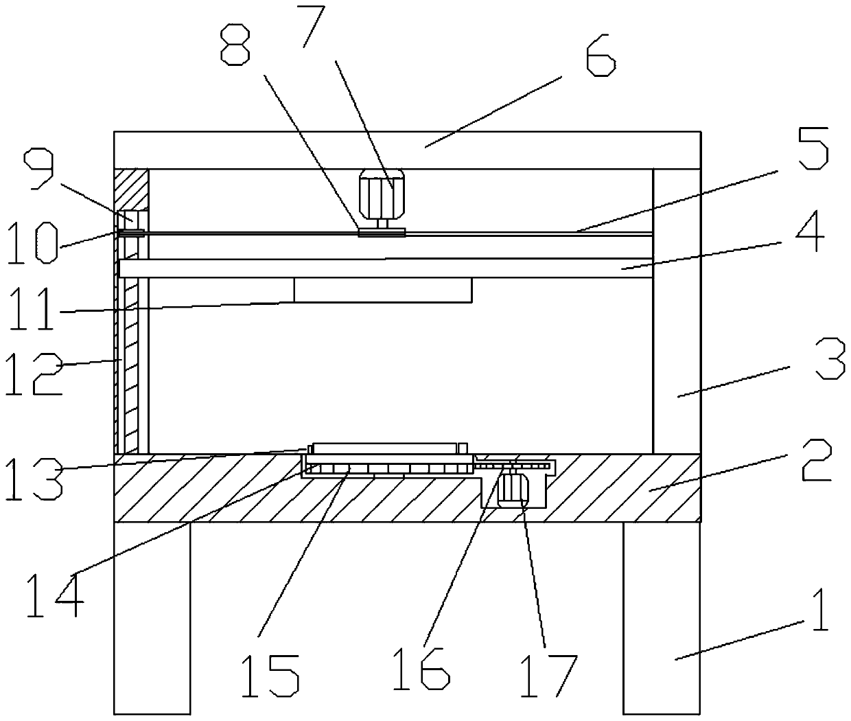
[0021] see Figure 1-2 , a grid-free printing plate of a cell, including a workbench 2 and a main body 11 of the printing plate. The four corners of the lower surface of the workbench 2 are fixed with vertical support legs 1 , and the support legs 1 have a supporting effect on the workbench 2 . The upper surface of the workbench 2 is symmetrically fixed with a vertical column 3 at the left and right ends, the top of the column 3 is connected by a horizontal push rod 6, and the lower surface of the middle position of the push rod 6 is fixedly installed with a first motor 7, the first motor The output shaft of 7 is coaxially connected with driving wheel 8. Driven by the first motor 7 , the drive wheel 8 rotates coaxially with the output shaft of the first motor 7 . The inside of the column 3 is provided with a mounting groove 12, and a vertical screw rod 9 is rotated in the mounting groove 12. The top end of the screw rod 9 is coaxially connected with a driven disc 10, and the...

Embodiment 2

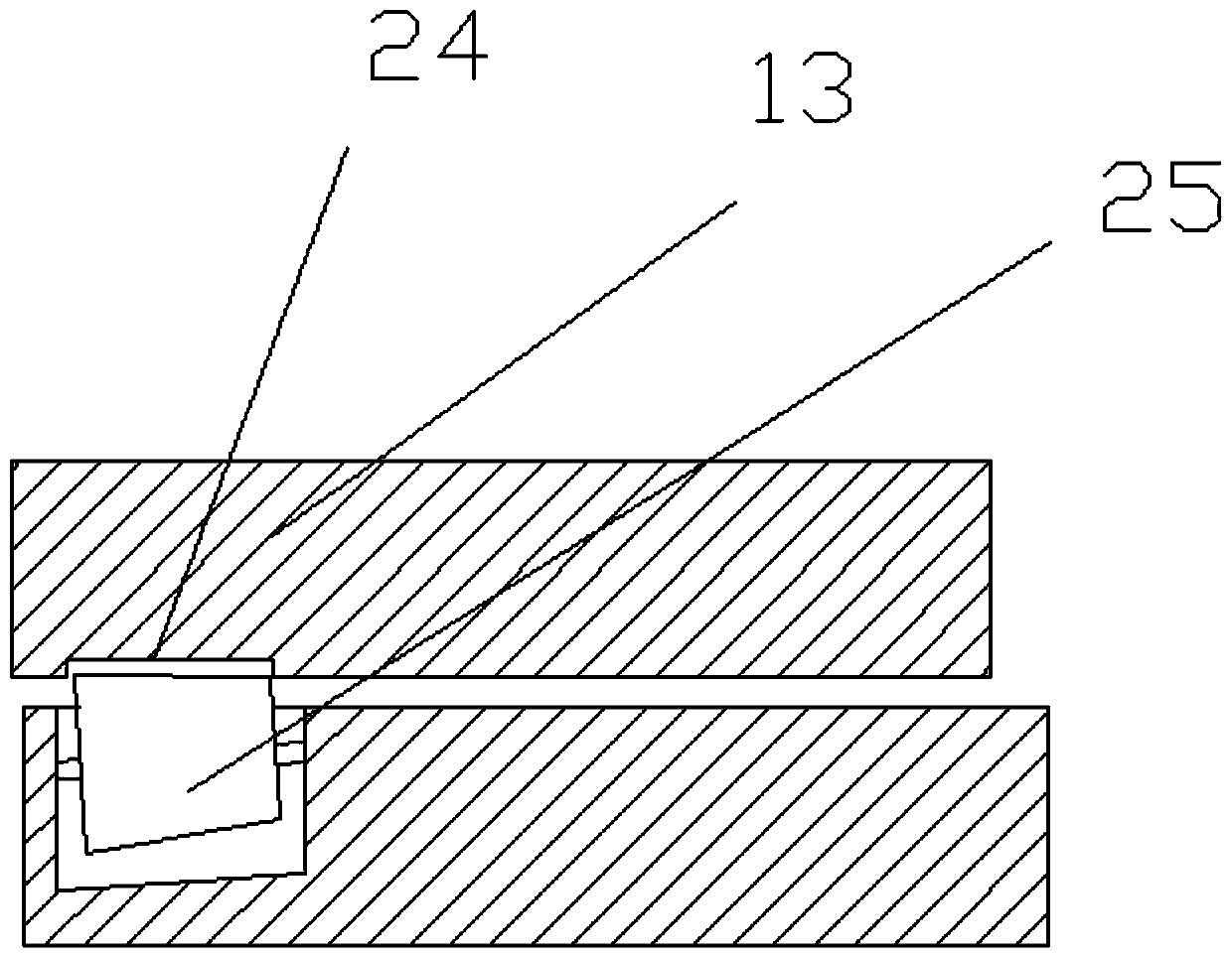
[0025] see image 3 On the basis of Embodiment 1, a circle of rolling grooves 24 is provided at the radial position of the lower surface of the rotating seat 14, and a running wheel 25 is arranged on the upper surface of the workbench 2 below the rolling groove 24, and the running wheels 25 are placed obliquely. Conical structure, the top of the runner 25 is nested inside the rolling groove 24, the runner 25 has a supporting effect on the clamping assembly 13, the setting of the runner 25 makes the rotation of the rotating seat 14 more stable and smooth.


PUM


Abstract

The invention relates to the technical field of printing plates, and particularly discloses a screen-free printing plate of a battery piece. The screen-free printing plate comprises a workbench and aprinting plate main body, vertical stand columns are symmetrically and fixedly arranged at the left end and the right end of the upper surface of the workbench, the top ends of the stand columns are connected through a horizontal ejector rod, the lower surface of the middle position of the ejector rod is fixedly provided with a first motor, an output shaft of the first motor is coaxially connectedwith a driving wheel, an installation groove is formed in each stand column, screw rods are rotatably arranged in the installation grooves, driven discs are coaxially connected to the top ends of thescrew rods, the printing plate main body is fixedly arranged on the lower surface of the middle position of a cross rod, the two ends of the cross rod are nested on the screw rods, a rotating base isrotatably arranged on the upper surface of the workbench, the edge of the rotating base is provided with teeth, the side edge of the rotating base is fixedly provided with a second motor inside the workbench, and an output shaft of a second motor is coaxially connected with a driving gear. The screen-free printing plate has the advantages of being simple in structure, stable in lifting, smooth inadjustment, high in printing quality and convenient to implement and popularize.

Description

technical field [0001] The invention relates to the technical field of printing plates, in particular to a grid-free printing plate of battery sheets. Background technique [0002] At present, the use of solar energy is more common. The most common use of solar energy is ultraviolet tubes and solar cells. The solar cell includes the solar cell body that plays a basic supporting role and the electrodes connected to the surface of the cell. The current generated by the cell derived via electrodes. The structure conducting current is the gate line. The grid lines are usually arranged in a horizontal and vertical cross mode. These grid line electrodes include horizontally arranged sub-grids and vertically arranged main grids, and the sub-grids and main grids are cross-connected as a whole; Electric energy, the generated current is collected on the auxiliary grid, and the auxiliary grid collects the current on the vertically arranged main grid and flows out from the main grid. ...

Claims


Application Information

Patent Timeline
Patent Type & Authority Applications(China)
IPC IPC(8): B41F15/36
CPCB41F15/36
Inventor 张志明
Owner 昆山乐邦精密科技有限公司
Why Eureka
Try Eureka