
Direct-pressing mode locking device for mechanical equipment

A technology of a mold clamping device and mechanical equipment, applied in the field of mechanical equipment, can solve the problems of low mold change efficiency, complicated operation, affecting production efficiency, etc., and achieve the effect of convenient mold clamping and mold change, simple and convenient operation, and improved work efficiency.

Inactive Publication Date: 2019-08-09
陈忠信
View PDF5 Cites 4 Cited by
  • Summary
  • Abstract
  • Description
  • Claims
  • Application Information

AI Technical Summary

Problems solved by technology

[0004] Traditional direct pressure mold clamping devices are mostly large-scale machines with complex structures, complex operations, and single functions, which are not suitable for small factories. At the same time, the efficiency of mold change is low, which indirectly affects production efficiency.

Method used


Image

  • Direct-pressing mode locking device for mechanical equipment
  • Direct-pressing mode locking device for mechanical equipment
  • Direct-pressing mode locking device for mechanical equipment

Examples


Embodiment Construction

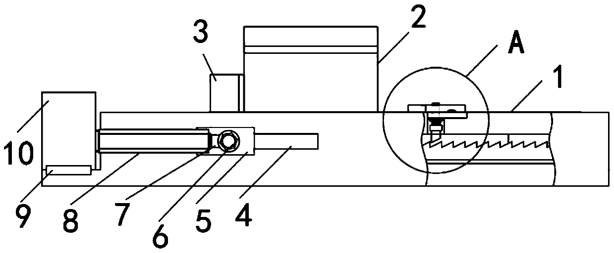
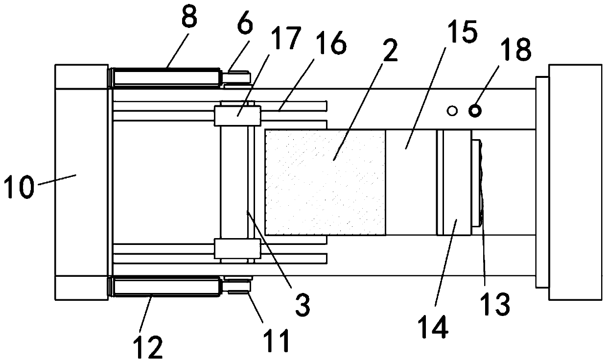
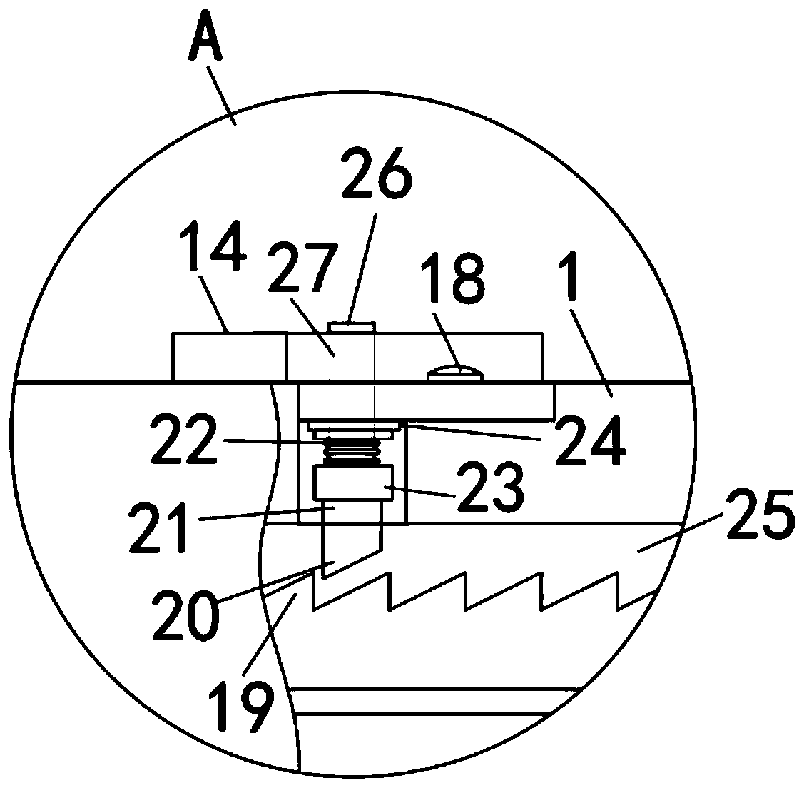
[0025] Such as Figure 1-3 As shown, this specific embodiment adopts the following technical solutions: a mechanical equipment direct pressure mold clamping device, including a mold clamping mechanism 1, a cylinder mold locking push plate 3 and a fine-tuning push plate 14, and both sides of the mold clamping mechanism 1 are provided with There is a side plate 10 of the mold locking mechanism, and a cylinder extension plate 9 is connected to each side of the side plate 10 of the mold locking mechanism. One side of the cylinder extension plate 9 is connected to the first push cylinder 8, and the other cylinder extension plate 9 One side is connected with the second cylinder 12, one side of the first cylinder 8 is connected with the first cylinder connecting shaft 6, one side of the second cylinder 12 is connected with the second cylinder connecting shaft 11, and the first cylinder connecting shaft 6 and the second cylinder connecting shaft 11 are located on both sides of the cla...


PUM


Abstract

The invention discloses a direct-pressing mold locking device for mechanical equipment. The direct-pressing mold locking device for mechanical equipment comprises a mold locking mechanism, an air cylinder mold locking push plate and a fine adjustment push plate, wherein the two sides of the mold locking mechanism are respectively provided with a mold locking mechanism side plate, and the two sidesof the mold locking mechanism side plate are respectively connected with an air cylinder extension plate. By placing a detachable direct-pressing mold in a limiting groove of the mold locking mechanism, the detachable direct-pressing mold can be pushed through a first push air cylinder and a second push air cylinder to be touched with the fine adjustment push plate. By adjusting the position of the fine adjustment push plate through a push plate pad, the detachable direct-pressing mold can be clamped and locked by the mold locking push plate for air cylinders and the fine adjustment push plate for air cylinders, so that a mold installation is achieved. Replacing of the mold has reverse operations. By resetting the first push cylinder and the second push cylinder and pressing an electromagnetic switch, a second electromagnetic ring is electrified to attract a first electromagnetic ring to drive a limiting gear block to ascend, and the position of the fine-adjustment push plate can be adjusted at will. The direct-pressing mold locking device for mechanical equipment has the advantages of simple and convenient operation, convenient die locking and die changing, and improved work efficiency of die locking and die changing in direct pressure production.

Description

[0001] Technical field: [0002] The invention belongs to the technical field of mechanical equipment, in particular to a direct pressure mold clamping device for mechanical equipment. [0003] Background technique: [0004] Traditional direct pressure mold clamping devices are mostly large-scale machines with complex structures, complex operations, and single functions, which are not suitable for small factories. At the same time, the efficiency of mold change is low, which indirectly affects production efficiency. [0005] Invention content: [0006] The object of the present invention is to provide a mechanical equipment direct pressure mold clamping device in order to solve the above problems, which solves the problems in the prior art. [0007] In order to solve the above problems, the present invention provides a technical solution of direct pressure mold clamping device for mechanical equipment: [0008] A direct pressure mold clamping device for mechanical equipment, ...

Claims


Application Information

Patent Timeline
Patent Type & Authority Applications(China)
IPC IPC(8): B29C33/24B29C33/32B29C33/30
CPCB29C33/24B29C33/30B29C33/306B29C33/32
Inventor 陈忠信
Owner 陈忠信
Learn More