Device for punching and cutting sucking disc part of electromagnetic clutch

An electromagnetic clutch and sucker technology, applied in the field of stamping dies, can solve problems such as difficult material removal, product outer diameter expansion, large material flow, etc., to achieve the effects of avoiding material flow, easy unloading, and convenient use

Active Publication Date: 2019-08-09
ANHUI HAOFANG ELECTROMECHANICS
View PDF5 Cites 1 Cited by
  • Summary
  • Abstract
  • Description
  • Claims
  • Application Information

AI Technical Summary

Problems solved by technology

[0004] The concentricity of the sucker part in the electromagnetic clutch drive plate assembly of the automobile air conditioner is relatively high, so the cooperation between the positioning part and the product in the production of the mold should use a sliding gap to ensure the position of the product, but in the stamping die punching Due to the thick material of the product during cutting, the material flow is relatively large during punching, which can easily cause the outer diameter of the product to expand, making it difficult to take out the product after stamping; The concentricity requirements of the product cannot be guaranteed

Method used


Image

  • Device for punching and cutting sucking disc part of electromagnetic clutch
  • Device for punching and cutting sucking disc part of electromagnetic clutch

Examples


Embodiment Construction

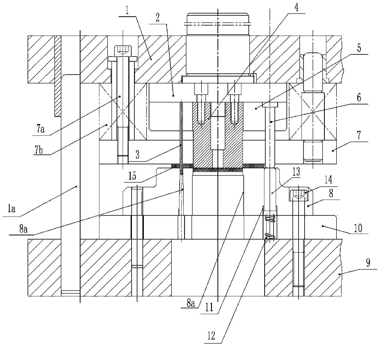
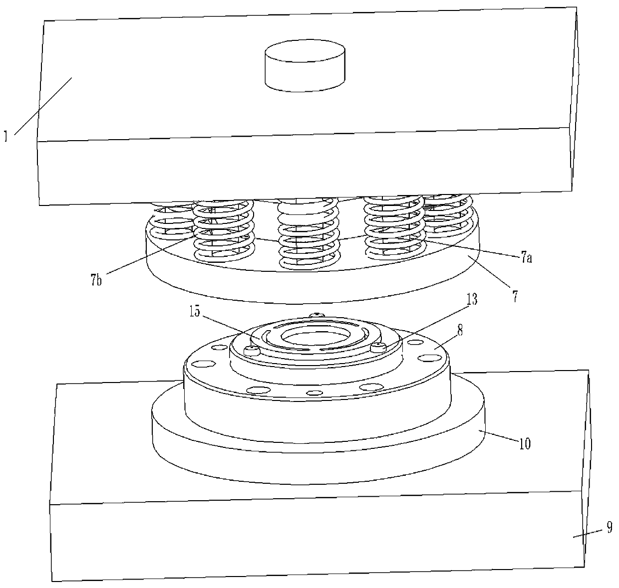
[0019] Such as figure 1 , 2 As shown, it includes an upper mold part and a lower mold part corresponding to each other. The upper mold part includes an upper template 1, an upper backing plate 2, and a coaxially distributed punch 4 is connected to the upper backing plate 2 by bolts, and the punch 4 is cylindrical. The upper backing plate 2 on the outside of the punch 4 is welded with a punch 3 whose lower end face is waist-shaped, and the upper backing plate 2 is connected with a fixed plate 5, and the fixed plate 5 is provided with the punch 4 and the punch 3 Corresponding matching relief holes, so that the lower end of the punch 4 and the punch 3 can pass through the fixing plate 5 . A stripping plate 7 is arranged below the fixed plate 5, and a group of guide rods 7a which form a sliding fit with the upper template 1 are evenly distributed on the stripping plate 7, and each guide rod between the upper template 1 and the stripping plate 7 The 7a shaft is covered with a bu...


PUM


Abstract

The invention provides a device for punching and cutting a sucking disc part of an electromagnetic clutch. The device for punching and cutting the sucking disc part of the electromagnetic clutch comprises an upper die plate (1), an upper base plate (2), a male die (3), a punch head (4), a fixed plate (5), ejector rods (6), an unloading plate (7), a lower die plate (9), a lower base plate (10) anda female die (8), and is characterized in that a group of installation holes (11) is arranged on the lower base plate (10) and the female die (8); a spring (12) and a positioning pin (13) are arrangedin each installation hole (11); and the positioning pins (13) and the ejector rods (6) form corresponding fit. The device for punching and cutting the sucking disc part of the electromagnetic clutchprovided by the invention is simple in structure and convenient to use, and has the advantages that the material flowing can be effectively avoided when the sucking disc part is punched and cut, the easiness in unloading is realized, the concentricity of a punched and cut waist slot and a center hole is qualified and the like.

Description

[0001] Technical field: [0002] The invention relates to a punching die, in particular to a punching device for electromagnetic clutch sucker parts. [0003] Background technique: [0004] The concentricity of the sucker part in the electromagnetic clutch drive plate assembly of the automobile air conditioner is relatively high, so the cooperation between the positioning part and the product in the production of the mold must use a sliding gap to ensure the position of the product, but in the stamping die punching Due to the thick product material during cutting, the material flow is relatively large during punching, which can easily cause the outer diameter of the product to expand, making it difficult to take out the product after stamping; if the transition fit is used, the matching gap between the positioning part and the product is increased, and The concentricity requirements of the product cannot be guaranteed. Therefore, there is an urgent need for a punching device t...

Claims


Application Information

Patent Timeline
Patent Type & Authority Applications(China)
IPC IPC(8): B21D28/14B21D28/04B21D45/04
CPCB21D28/04B21D28/14B21D45/04
Inventor 杜朝晖许静王荣胜
Owner ANHUI HAOFANG ELECTROMECHANICS
Why Eureka
Try Eureka