Continuous type centrifugal machine used for cell separation
A centrifuge and cell technology, applied in the direction of centrifuge, etc., can solve the problems of cell activity, cumbersome centrifugation operation, etc., and achieve the effect of improving centrifugation efficiency, simple and reasonable operation, and ensuring a sterile environment
- Summary
- Abstract
- Description
- Claims
- Application Information
AI Technical Summary
Problems solved by technology
Method used
Image
Examples
specific Embodiment approach 1
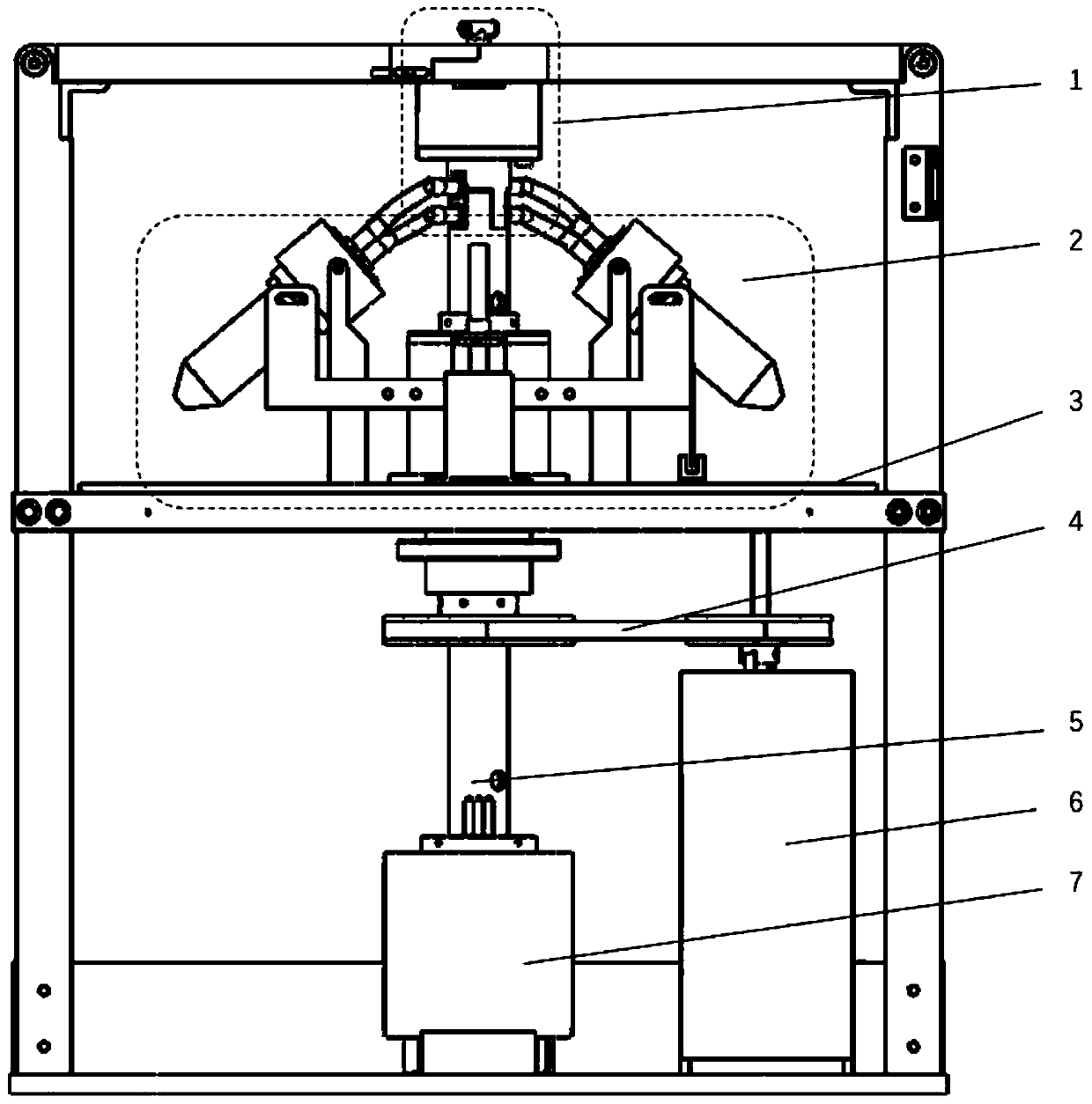
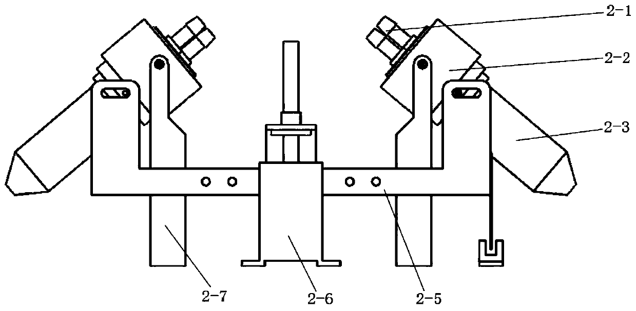
[0012] Specific implementation mode one: combine Figure 1-Figure 4 Describe this embodiment, a continuous centrifuge for cell separation described in this embodiment, which includes a rotary closed liquid inlet module 1, a swing stirring mechanism 2, a rotating platform 3, a transmission mechanism 4, a hollow main shaft 5, and a drive motor 6 and the conductive slip ring 7; the drive motor 6 is set close to the conductive slip ring 7, the bottom end of the hollow main shaft 5 is fixedly installed on the rotor shaft of the conductive slip ring 7, and the top of the hollow main shaft 5 passes through the rotating platform 3 and the rotary sealing liquid inlet module 1 The bottom end of the hollow main shaft 5 is fixed, the outer wall of the hollow main shaft 5 is fixedly connected with the rotating platform 3, the shell of the rotary closed liquid inlet module 1 is fixedly connected with the fixed frame, the output end of the rotating shaft of the driving motor 6 is connected wi...
specific Embodiment approach 2
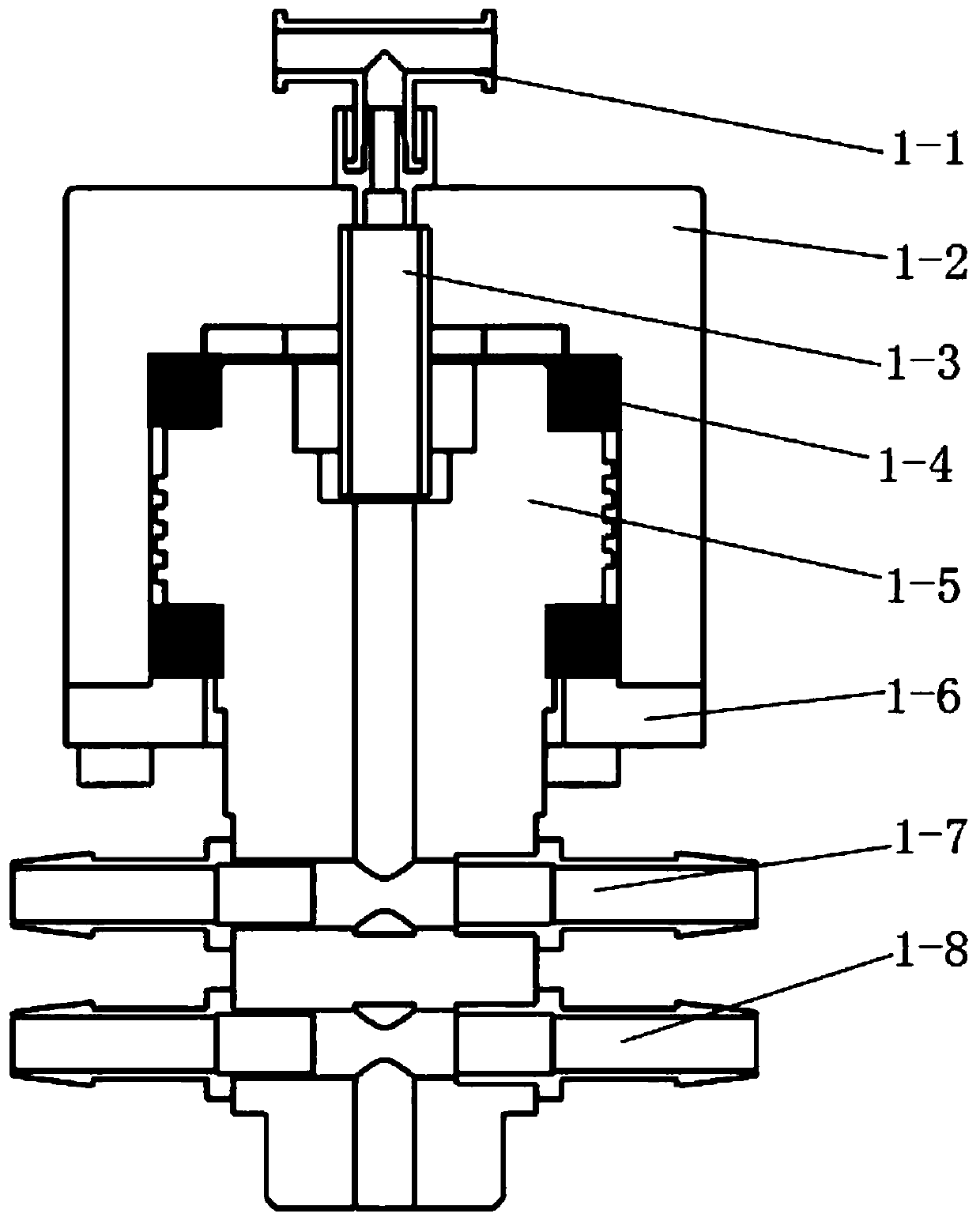
[0013] Specific implementation mode two: combination figure 2 Describe this embodiment, a continuous centrifuge for cell separation described in this embodiment, the rotary seal liquid inlet module 1 includes a liquid inlet pipe 1-1, a rotary seal seat 1-2, a throat 1-3, a neck Tube 1-5, sealing cover 1-6, two rotary sealing rings 1-4, two neck tube liquid outlet joints 1-7 and two neck tube liquid inlet joints 1-8; the outer wall of the rotary seal seat 1-2 It is fixedly connected with the fixed frame, the liquid inlet pipe 1-1 is sealed and connected with one end of the throat pipe 1-3, the throat pipe 1-3 is inserted into the inner cavity at the top of the rotary sealing seat 1-2, and the top end of the neck pipe 1-5 protrudes The upper end of the neck tube 1-5 is installed in the shell of the rotary seal seat 1-2, and the raised top and bottom end of the neck tube 1-5 are connected and installed in the shell of the rotary seal seat 1-2 through two rotary seal rings 1-4. ...
specific Embodiment approach 3
[0014] Specific implementation mode three: combination figure 2 This embodiment is described. In the continuous centrifuge for cell separation described in this embodiment, the convex outer circular surface at the top of the neck tube 1-5 is processed with external threads. The screwing direction of the protruding external thread of the neck tube 1-5 is the same as the rotation direction of the neck tube 1-5, and there is a seal between the rotating seal seat 1-2, the protrusion of the neck tube 1-5 and the two rotating sealing rings 1-4. The lubricating liquid drives the lubricating liquid to move upward through the rotation of the neck tube 1-5, thereby increasing the sealing effect between the rotating sealing ring 1-4 and the neck tube 1-5. Other methods are the same as in the first embodiment.
PUM
 Abstract
Description
Claims
Application Information
 - R&D
- Intellectual Property
- Life Sciences
- Materials
- Tech Scout
- Unparalleled Data Quality
- Higher Quality Content
- 60% Fewer Hallucinations
Browse by: Latest US Patents, China's latest patents, Technical Efficacy Thesaurus, Application Domain, Technology Topic, Popular Technical Reports.
© 2025 PatSnap. All rights reserved.Legal|Privacy policy|Modern Slavery Act Transparency Statement|Sitemap|About US| Contact US: help@patsnap.com


