Protection and filtering device for underwater sensor

An underwater sensor and filter device technology, applied in sampling device, filter loop, filter separation and other directions, can solve problems such as affecting water sample collection and extraction, affecting measurement signal, instrument attachment, etc., to slow down the adhesion process, increase working time, The effect of reducing replacement time and replacement frequency

Active Publication Date: 2019-08-06
SECOND INST OF OCEANOGRAPHY MNR
View PDF7 Cites 2 Cited by
  • Summary
  • Abstract
  • Description
  • Claims
  • Application Information

AI Technical Summary

Problems solved by technology

[0003] There are two types of underwater sensors, one is based on optical or electrochemical direct measurement sensors, and the other is based on wet chemical method after sampling measurement instruments. In actual operation, such problems are often encountered. In coastal waters During the investigation, due to the high turbidity of the water body, the complex base, and the vigorous growth of algae, the sensor is easily disturbed by suspended particles, dissolved organic matter, and water flow after deployment, which will affect the measurement signal, or cause blockage that affects the collection and extraction of water samples, and After a period of deployment, the instrument is often seriously attached by organisms, causing blockage and other instrument failures, and cannot be used for long-term deployment. It is necessary for scientific researchers to maintain and re-deploy the equipment. For this reason, we propose a method for Protection and filtration devices for underwater sensors. At present, although there are many filtration device manufacturers, their products are concentrated in laboratory use or on-line filtration (such as traditional filter membranes, needle filters, etc.), and there is no demand as mentioned above. product appears

Method used


Image

  • Protection and filtering device for underwater sensor
  • Protection and filtering device for underwater sensor
  • Protection and filtering device for underwater sensor

Examples


Embodiment Construction

[0023] The technical solutions in the embodiments of the present invention will be clearly and completely described below in conjunction with the accompanying drawings in the embodiments of the present invention. Obviously, the described embodiments are only some of the embodiments of the present invention, not all of them. Based on the embodiments of the present invention, all other embodiments obtained by persons of ordinary skill in the art without creative work all belong to the protection scope of the present invention.

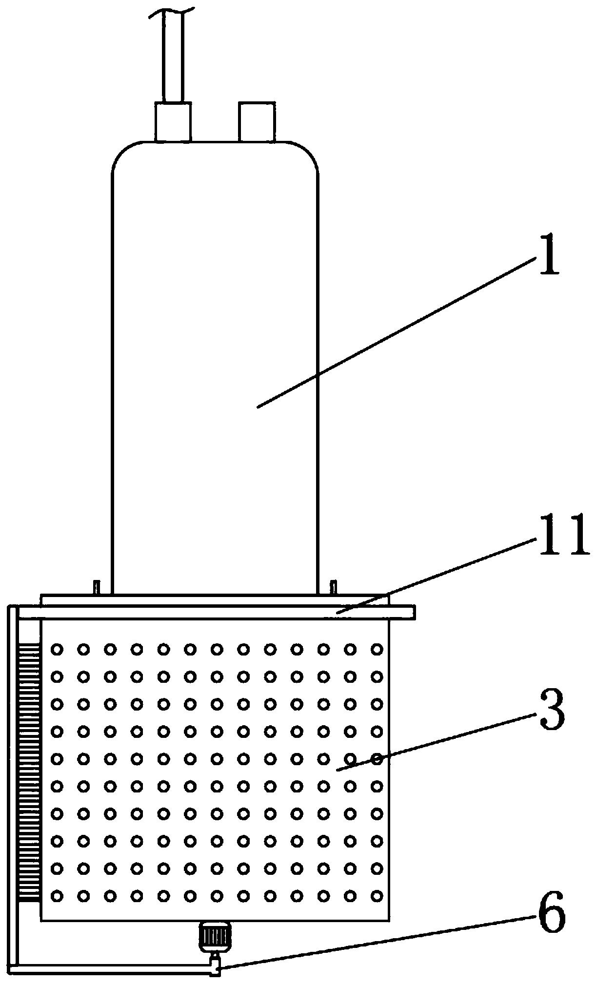
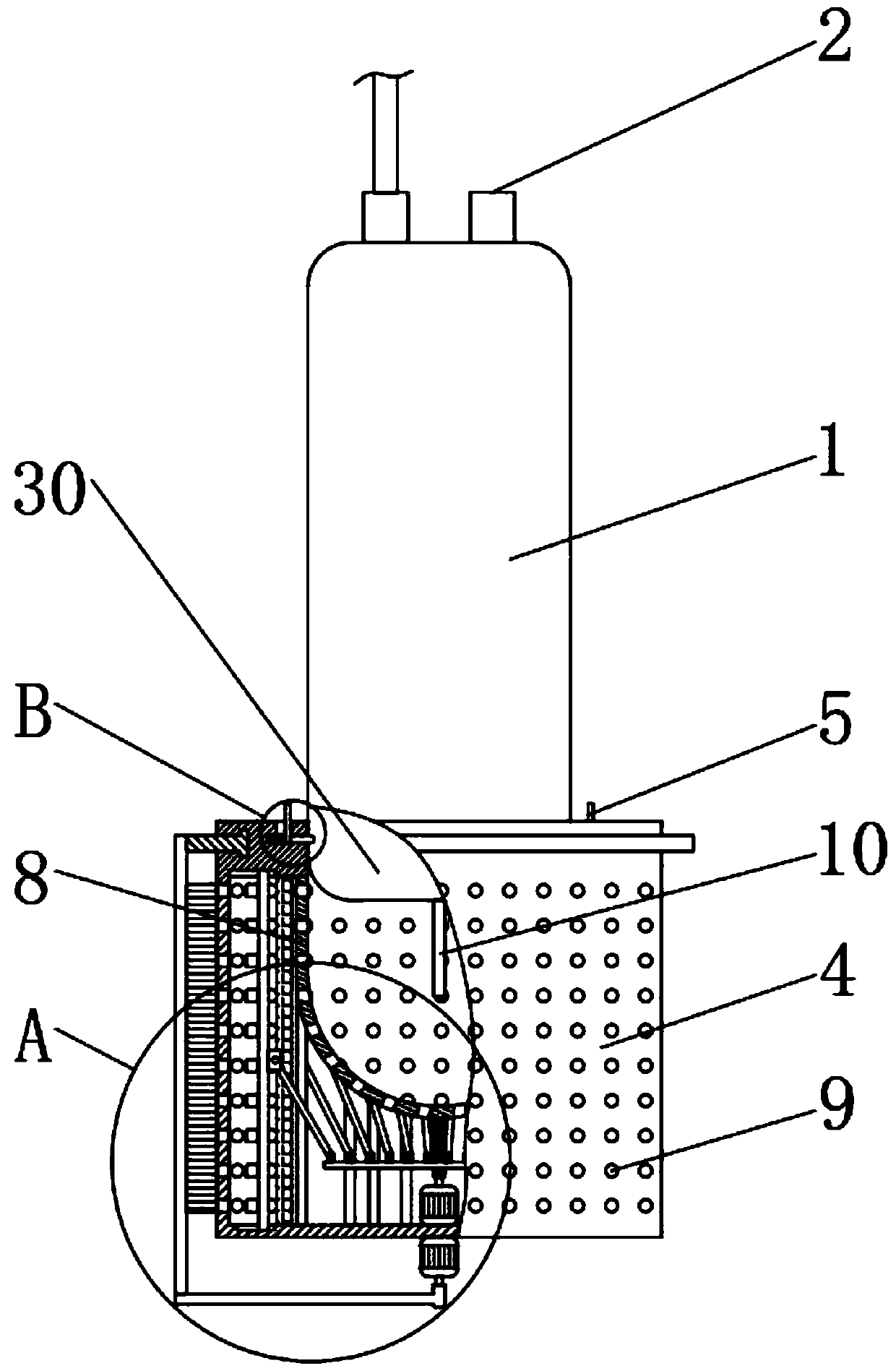
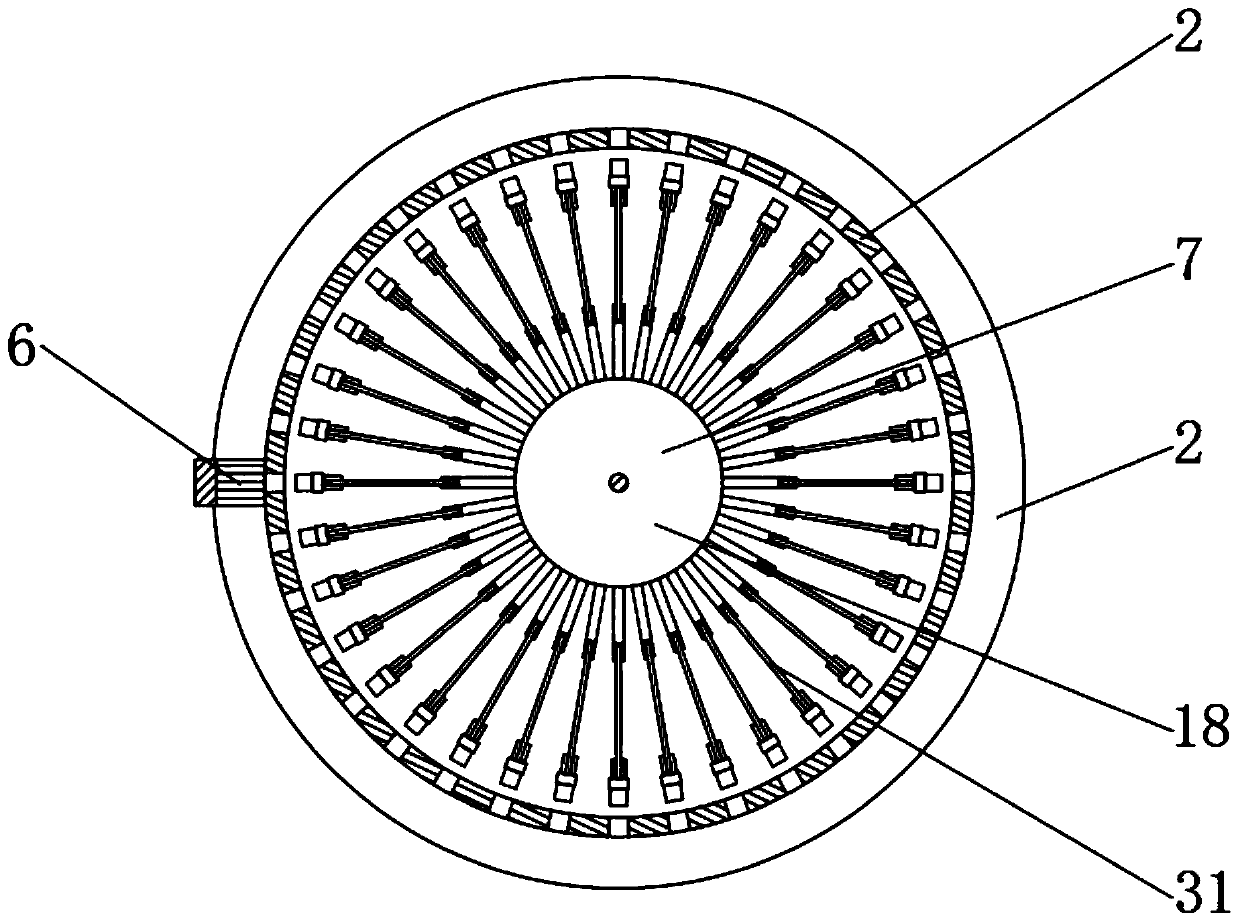
[0024] see Figure 1-5 , the present invention provides a technical solution: a protection and filtering device for underwater sensors, including a protection device 3, a sensor detection probe 30 is fixed on the top of the protection device 3, and the sensor detection probe 30 includes a pressure-resistant chamber 1. The watertight joint 2 and the underwater detection sensor 10, the underwater detection sensor 10 is arranged inside the protection device...


PUM


Abstract

The invention discloses a protection and filtering device for an underwater sensor. The device comprises a protection device. A sensor monitoring probe is fixed on the top of the protection device andincludes a pressure-resistant cabin, a watertight joint and an underwater detecting sensor. The underwater detecting sensor is arranged inside the protection device. According to the protection and filtering device, with the protection device, the underwater detecting sensor and a water inlet are protected from being impacted and damaged to a certain degree. The parts are made of copper materialsexcept the filler; the attachment process of the organism can be reduced effectively because of the own biotoxicity of the copper; the through hole formed in an outer copper mesh and the inner fillerform a two-stage filtering device and thus large-particle-size suspension particles and living bodies like silt can be removed basically even though not all suspension particles can be removed completely, thereby ensuring the relative cleanness of sea water in the protection device and increasing the underwater working time of the sensor.

Description

technical field [0001] The invention relates to the technical field of marine underwater sensor detection, in particular to a protection and filtering device for underwater sensors. Background technique [0002] At present, my country's marine observation technology, especially the observation technology of marine chemistry, is still dominated by sampling observations at large surface stations of survey ships and mooring submersible / buoy observations. Online monitoring technologies and in-situ observation technologies are also being developed and popularized. Among them, moored submersible / buoy observation and on-line and in-situ observation can effectively avoid possible contamination problems during sample collection and storage, as well as chemical form changes that may exist during sampling, storage, and analysis due to changes in temperature and pressure. And concentration changes, not only can obtain high-resolution observation data in time, but also obtain the tempora...

Claims


Application Information

Patent Timeline
Patent Type & Authority Applications(China)
IPC IPC(8): G01N33/18G01N1/14B01D36/02
CPCB01D36/02G01N1/14G01N33/18
Inventor 朱勇杨志张振华陈建芳
Owner SECOND INST OF OCEANOGRAPHY MNR
Why Eureka
Try Eureka