Novel internal combustion truck energy supply system and method coupled with vehicle air conditioner

An energy supply system, a technology for internal combustion trucks, applied in vehicle components, air handling equipment, heating/cooling equipment, etc., can solve the problems of increasing system complexity, vehicle load, overall performance impact, and low utilization of AC equipment. The effect of improving fuel efficiency, reducing total weight and compact structure

Pending Publication Date: 2019-08-06
NANJING UNIV OF AERONAUTICS & ASTRONAUTICS
View PDF4 Cites 0 Cited by
  • Summary
  • Abstract
  • Description
  • Claims
  • Application Information

AI Technical Summary

Problems solved by technology

[0005] According to the review, although adding ORC can effectively improve the overall energy efficiency of the vehicle, it will also increase the complexity of the system and the vehicle load; few scholars choose to couple the ORC system with the air conditioner (AC) system to compensate The defect

Method used


Image

  • Novel internal combustion truck energy supply system and method coupled with vehicle air conditioner

Examples


Embodiment Construction

[0027] Below in conjunction with accompanying drawing and embodiment the present invention is described in further detail:

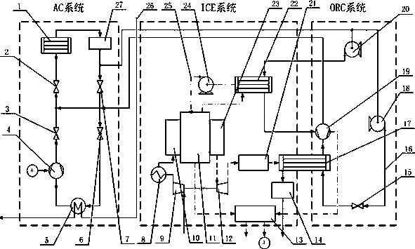
[0028] The ORC coupled diesel engine energy system diagram is shown in the attached figure, which consists of ICE, ORC and AC subsystems.

[0029] The specific thermal process of the ICE system is as follows: the air 26 is compressed by the air supercharger 9, the pressure and temperature rise slightly, and then enters the intercooler 8 for cooling, the static temperature drops, and the static pressure remains unchanged, and then enters the suction port 10 of the internal combustion engine for further processing. Compression, the pressure is greatly increased, and the internal combustion engine 11 is burned, and part of the heat released by the combustion is cooled by the coolant 25 and discharged into the atmosphere, most of which are used to increase the temperature of the gas. The exhaust turbine 12 continues to expand to atmospheric pressure, drives ...


PUM


Abstract

The invention relates to a novel internal combustion truck energy supply system and method coupled with a vehicle air conditioner, and belongs to the field of energy and power. The system is characterized in that the ORC coupled diesel engine energy system waste heat collection is from a first evaporator (5); an organic Rankine cycle subsystem of the system comprises a turbine (19), a low-pressureworking medium pump (20) and a high-pressure working medium pump (18). Compared with an existing related composite power system and method for recycling vehicle smoke waste heat, the system is mainlycharacterized in that the turbine (19) and the low-pressure working medium pump (20) are additionally arranged, so the energy utilization rate is increased, and heat emission is reduced. A telescopicbutterfly valve is adopted, so that backflow is avoided.

Description

technical field [0001] The invention relates to a novel internal combustion truck energy supply system and method coupled with a vehicle air conditioner, belonging to the field of energy and power. Background technique [0002] Diesel locomotives have a wide range of applications. However, its current heat conversion efficiency is only about 40%, and the remaining energy is mainly discharged to the environment in the form of waste heat, while the waste heat of the coolant accounts for 20-30%, and the exhaust waste heat accounts for 30-40%. Further improving its energy utilization efficiency and reducing pollution emissions is its future development trend. [0003] From the perspective of engine efficiency alone, it is very difficult to improve fuel utilization from the perspective of combustion after the direct injection gasoline engine technology and homogeneous charge compression combustion technology are adopted. [0004] In recent years, the use of ORC system to recove...

Claims


Application Information

Patent Timeline
IPC IPC(8): B60H1/00B60H1/32B60H1/20
CPCB60H1/00378B60H1/3232B60H1/3229B60H1/20
Inventor 刘晟奕罗中岐强恣懿程胜涛易子琰岳晨
Owner NANJING UNIV OF AERONAUTICS & ASTRONAUTICS
Why Eureka
Try Eureka