
Simple laser intersecting line cutting machine

A laser cutting and intersecting line technology, which is applied in laser welding equipment, welding equipment, metal processing equipment, etc., can solve the problems of high price and lack of simple intersecting line cutting machine

Active Publication Date: 2019-08-06
苏州普拉托激光科技有限公司
View PDF10 Cites 3 Cited by
  • Summary
  • Abstract
  • Description
  • Claims
  • Application Information

AI Technical Summary

Problems solved by technology

[0008] The technical problem to be solved by the present invention is: to solve the problem that the CNC intersecting wire cutting machine in the prior art is expensive and lacks a simple intersecting wire cutting machine

Method used


Image

  • Simple laser intersecting line cutting machine
  • Simple laser intersecting line cutting machine
  • Simple laser intersecting line cutting machine

Examples


Embodiment 1

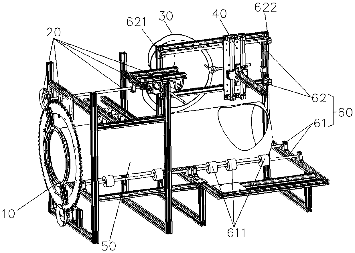
[0061] The invention provides a simple laser intersecting line cutting machine, such as figure 1 and Image 6 As shown, it includes: a pipe clamping fixture 10, a gear transmission assembly 20, a cam 30 and a laser cutting assembly 40;

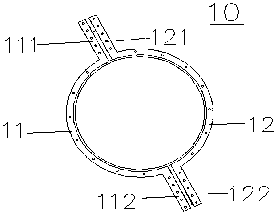
[0062] The pipe clamping fixture 10 is used for clamping the pipe material 50 to be cut;

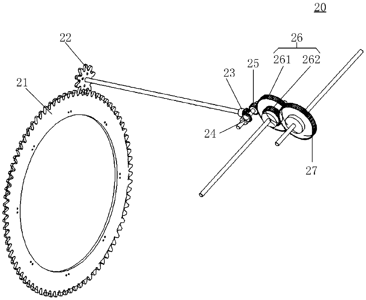
[0063] The gear transmission assembly 20 is connected with the pipe clamping fixture 10 , and the gear transmission assembly 20 rotates with the rotation of the pipe material 50 to be cut, wherein the gear transmission assembly 20 and the pipe clamping fixture 10 floating connection;

[0064] The gear transmission assembly 20 is connected to the cam 30, the gear transmission assembly 20 drives the cam 30 to rotate, and the cam 30 is used to generate the trajectory of the intersecting lines of the pipe material 50 to be cut;

[0065] The laser cutting assembly 40 includes a first sliding frame 41, a cam thimble 42 and a laser cutting head 43, and the c...

Embodiment 2

[0082] In a specific application scenario, in order to facilitate the cutting of intersecting lines on pipes, for example, when cutting intersecting lines on the same pipe, both radial intersecting lines and axial intersecting lines need to be cut on the same pipe. At this time, it is necessary to switch from the cam 30 for cutting radial intersecting lines to the cam 70 for cutting axial intersecting lines, and to replace the cam again, which is very troublesome and wastes man-hours. In order to switch from radial intersecting line cutting to axial intersecting line cutting conveniently and quickly, or convert axial intersecting line cutting to radial intersecting line cutting, the second embodiment of the present invention adopts the cam 30 Installed side by side with the cam 70, and installed on the simple laser intersecting line cutting machine at the same time, it can rotate with the gear transmission assembly 20 at the same time, so that the radial intersecting line and t...


PUM


Abstract

The invention discloses a simple laser intersecting line cutting machine. A pipe clamping fixture is used for clamping a to-be-cut pipe, a gear driving assembly is in floating connection with the pipeclamping fixture and is used for rotatably and synchronously transferring the to-be-cut pipe to a cam, and the cam is used for generating the track of an intersecting line of the to-be-cut pipe; a laser cutting assembly comprises a cam ejector pin, a first sliding frame and a laser cutting head, the cam ejector pin makes contact with the cam and does a reciprocating linear motion along with the rotation of the cam, the laser cutting head and the cam ejector pin synchronously do the reciprocating linear motion, the cutting track of the intersecting line is determined according to the path of the reciprocating linear motion of the cam ejector pin, and the rotation of the to-be-cut pipe is matched, so that the intersecting line of the to-be-cut pipe is cut by the laser cutting head. According to the simple laser intersecting line cutting machine provided by the embodiment of the invention, a cam mechanism is adopted, the precision is high, the operation is simple, the cost is low, and the maintenance is easy.

Description

[0001] 【Technical field】 [0002] The invention relates to the technical field of laser cutting, in particular to a simple laser intersecting line cutting machine. [0003] 【Background technique】 [0004] In the machining process, the common methods of pipe cutting are manual cutting, semi-automatic cutting machine cutting and intersecting wire cutting machine cutting. Manual cutting is flexible and convenient, but the quality of manual cutting is poor, the size error is large, the material waste is large, the subsequent processing workload is large, and the labor conditions are harsh and the production efficiency is low. Although other types of semi-automatic cutting machines reduce the labor intensity of workers, they have simple functions and are only suitable for cutting parts with relatively regular shapes. [0005] When railings, pipes, etc. are connected, intersecting line cutting processing is required for pipe structural parts. In the past, most of such processing use...

Claims


Application Information

Patent Timeline
IPC IPC(8): B23K26/08B23K26/38
CPCB23K26/083B23K26/38
Inventor 林权原梓皓陈财炜
Owner 苏州普拉托激光科技有限公司
Learn More