
Automatic roll material machining device, laser marking system and roll material machining method

A technology of processing device and driving device, which is applied in the field of marking, can solve the problems such as the deformation of the material tape and the influence of the material tape on the discharge reel, so as to improve the quality, facilitate the collection of the material tape, and facilitate the effect of marking

Active Publication Date: 2019-08-06
HANS LASER TECH IND GRP CO LTD
View PDF14 Cites 4 Cited by
  • Summary
  • Abstract
  • Description
  • Claims
  • Application Information

AI Technical Summary

Problems solved by technology

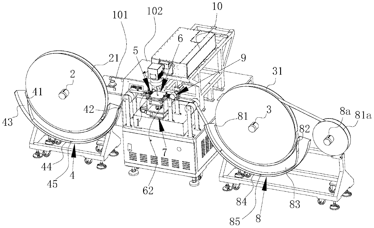
[0005] One of the objectives of the present invention is to provide an automatic coil processing device to solve the problem in the prior art that during the conveying and marking process of the material tape, the periphery of the coiled material tape on the feed reel is easily damaged. Under the action of gravity, relaxation occurs, so that the material belt is deformed, which affects the technical problem that the material belt is wound on the discharge reel

Method used


Image

  • Automatic roll material machining device, laser marking system and roll material machining method
  • Automatic roll material machining device, laser marking system and roll material machining method
  • Automatic roll material machining device, laser marking system and roll material machining method

Examples


Embodiment Construction

[0042]In order to make the technical problems, technical solutions and beneficial effects to be solved by the present invention clearer, the present invention will be further described in detail below in conjunction with the accompanying drawings and embodiments. It should be understood that the specific embodiments described here are only used to explain the present invention, not to limit the present invention.

[0043] It should be noted that when an element is referred to as being “fixed” or “disposed on” another element, it may be directly on the other element or be indirectly on the other element. When an element is referred to as being "connected to" another element, it can be directly connected to the other element or indirectly connected to the other element.

[0044] It is to be understood that the terms "length", "width", "top", "bottom", "front", "rear", "left", "right", "vertical", "horizontal", "top" , "bottom", "inner", "outer" and other indicated orientations ...


PUM


Abstract

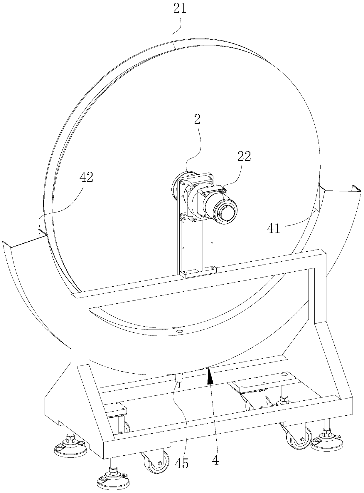
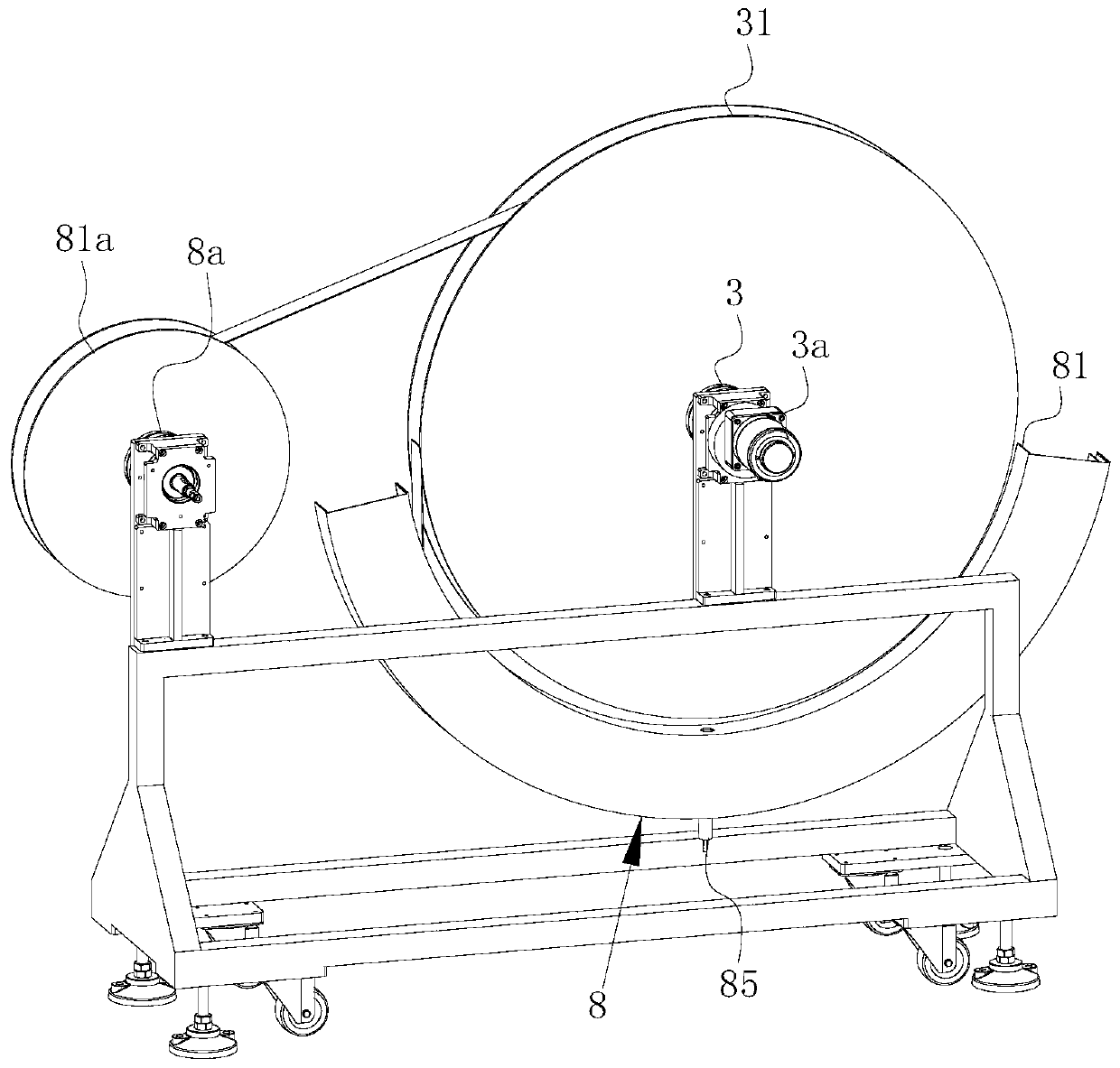
The invention provides an automatic roll material machining device. The automatic roll material machining device comprises a carrying platform, a feeding roll, a material collecting roll and a material collecting driving motor; the feeding roll is arranged on one side of the carrying platform and used for winding unmarked material strips; the material collecting roll is arranged on the side, opposite to the feeding roll, of the carrying platform and used for winding marked material strips; the material collecting driving motor is connected to the material collecting roll and used for driving the material collecting roll to rotate; and the automatic roll material machining device further comprises a first anti-deformation mechanism, the first anti-deformation mechanism is arranged on the outer side of the feeding roll and provided with a feeding port and a discharging port, the feeding port faces the roll surface of the feeding roll, a buffering cavity communicating with the feeding port and the discharging port is formed in the first anti-deformation mechanism, the buffering cavity is provided with a buffering surface parallel to the circumferential direction of the feeding roll, and the buffering surface is used for making contact with the back faces of the material strips and located between the feeding port and the discharging port. The invention further provides a laser marking system and a roll material machining method. The purpose that the roll materials are not prone to being deformed in the laser marking process is achieved.

Description

technical field [0001] The invention belongs to the technical field of marking, and more specifically relates to a coil material automatic processing device, a laser marking system and a coil material processing method. Background technique [0002] Laser marking is a marking method that uses a high-energy-density laser to locally irradiate the workpiece to vaporize the surface material or undergo a chemical reaction of color change, thereby leaving a permanent mark. Laser marking can print various characters, symbols and patterns, etc., and the character size can range from millimeters to microns, which has special significance for product anti-counterfeiting. [0003] When laser marking the material tape, the material tape is usually wound on the feed reel, the feed reel is set on one side of the carrier, and the output reel is also set on the other side of the carrier. , the discharge reel is connected with a drive motor that drives its rotation. When the material belt ...

Claims


Application Information

Patent Timeline
Patent Type & Authority Applications(China)
IPC IPC(8): B23K26/08B23K26/362
CPCB23K26/0846B23K26/362
Inventor 郭缙曹洪涛刘亮杨柯陈日帅梁华亮许锦坤李金恒胡述旭何起健吕启涛高云峰
Owner HANS LASER TECH IND GRP CO LTD
Learn More