Microgrid group cross-domain coordination energy scheduling and adaptive optimization cooperative operation method

A technology of energy scheduling and operation methods, applied in the direction of instruments, data processing applications, forecasting, etc., can solve the problems of unable to provide continuous and stable power supply, limited effect of energy storage units, losses, etc., to achieve convenient combination and split use, improve The effect of improving algorithm efficiency and utilization

Pending Publication Date: 2019-08-02
苏州求臻智能科技有限公司
View PDF4 Cites 0 Cited by
  • Summary
  • Abstract
  • Description
  • Claims
  • Application Information

AI Technical Summary

Problems solved by technology

However, although there are relatively stable and reliable power supply systems such as internal combustion generators and gas turbine generators among the currently commonly used distributed power sources, their scale and power supply will be limited to a certain extent because they need to consume traditional energy for power supply. It meets the power consumption requirements of all power loads in the micro-grid, and solar and wind power generation systems are more infiltrated into the micro-grid system because of their clean and renewable characteristics.
However, due to the influence of weather, environment and other factors, the latter has the characteristics of intermittent and fluctuating power supply, so it cannot provide continuous and stable power supply.
[0003] This will reduce the operating efficiency of the autonomous microgrid system from two aspects:
[0004] On the one hand, when the DG power supply is sufficient, a large amount of electric energy will not be effectively utilized
Although the energy storage device can absorb part of the excess power at this time, its effect is limited and a large number of energy storage units are required, which greatly increases the investment and maintenance costs of the microgrid system;
[0005] On the other hand, when the DG power supply is insufficient, the load cannot receive sufficient power supply and is limited, especially when the CL power supply in the system is insufficient, the losses will be more serious

Method used


Image

  • Microgrid group cross-domain coordination energy scheduling and adaptive optimization cooperative operation method
  • Microgrid group cross-domain coordination energy scheduling and adaptive optimization cooperative operation method
  • Microgrid group cross-domain coordination energy scheduling and adaptive optimization cooperative operation method

Examples


Embodiment

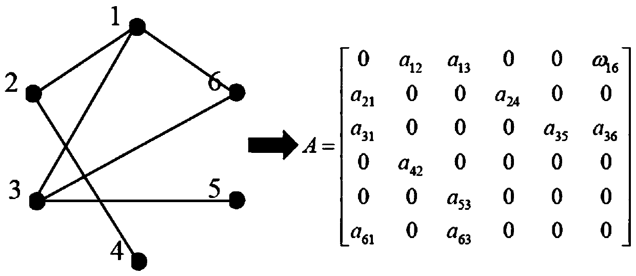
[0062] see image 3 , using IEEE 33 node topology to divide the network, its topology is as follows Figure 4 shown.

[0063] Depend on Figure 4 It can be seen that there are 3 DGs in the entire network, among which DG is set 1 For photovoltaic (0-624.205MW), DG 2 and DG 3 It is wind energy (82.01-419.50MW), and its power characteristic curve comes from Belgian electricity transmissionoperator Elias (May 13 th ,2014), such as Figure 5 (a) shown. Each energy storage unit is set to have a maximum capacity of 900MWh, then Figure 4 The maximum total capacity of the energy storage system in the system shown is 2700MWh. also, Figure 4 The system shown contains 6 important loads and 21 non-important loads, and its typical 24h working characteristic curve is as follows Figure 5 (b) shown. The connection types of each node are shown in Table I.

[0064] TABLEI

[0065] NODES CONNECTED WITH DGS CLS AND NLS IN33-BUS TEST SYSTEM

[0066]

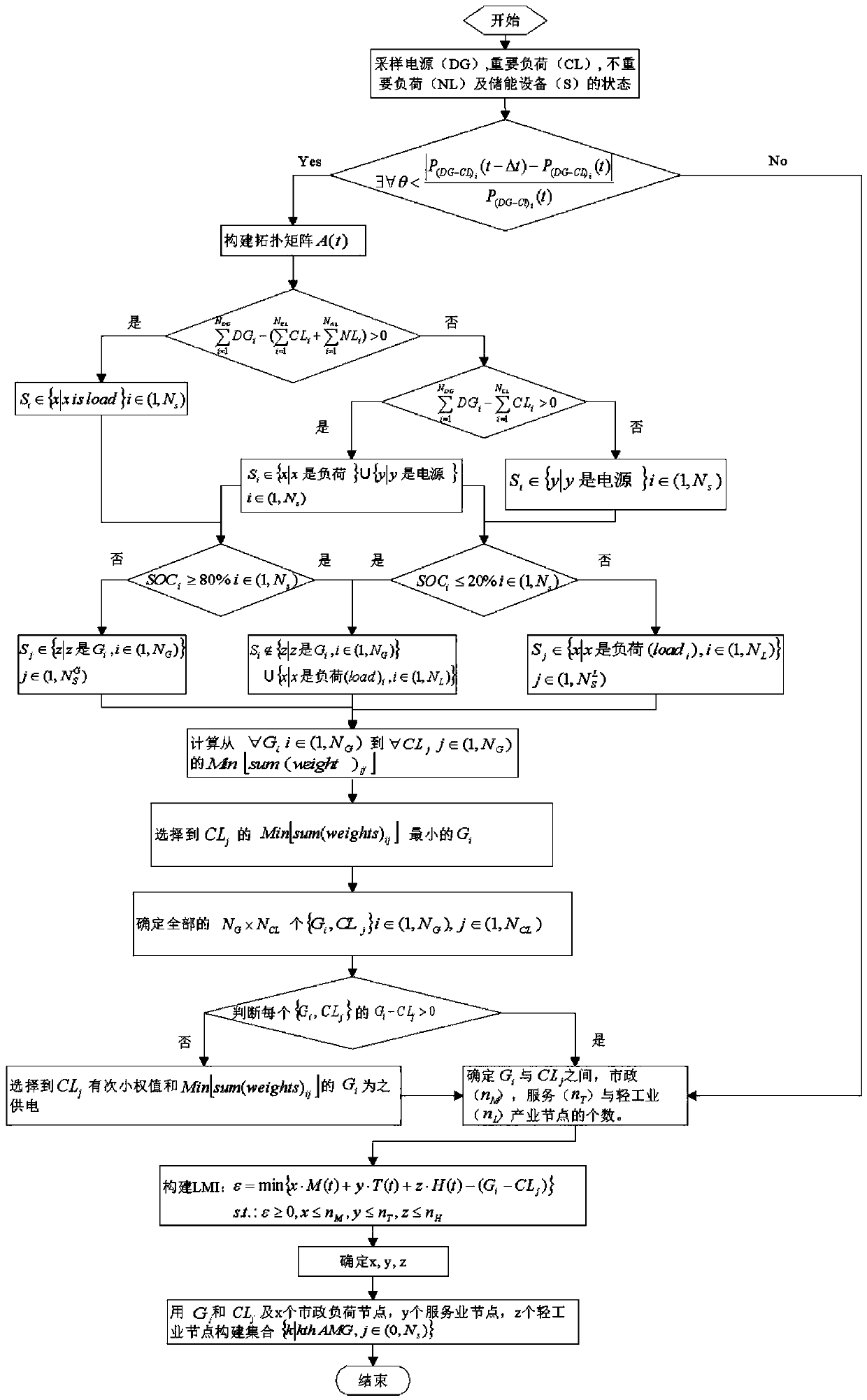
[0067] (1) Sampling at the ...


PUM


Abstract

The invention discloses a microgrid group cross-domain coordination energy scheduling and adaptive optimization cooperative operation method. The method comprises: for a tertiary-level layer in a micro-grid system, considering monitoring equipment connected with a switch through a power system, for example, a multi-agent, acquiring system state information, controlling an interconnection switch byusing the system state information, reconstructing a microgrid topological structure from a logic level, optimizing and combining power supply and consumption systems of a plurality of autonomous microgrid systems again, and realizing optimized scheduling of electric energy through cooperation; a 'stem leaf generation strategy' mainly comprising two algorithms, namely, MST searching an optimal DG-CL power supply relation, determining a network basic system; and the LMI determining the addition or deletion of the NL node, so that the maximum utilization of the DG electric energy is ensured.

Description

technical field [0001] The invention relates to the field of distributed power generation and energy storage equipment of a microgrid system, in particular to a method for cross-domain coordinated energy scheduling and adaptive optimization cooperative operation of a microgrid group including wind, solar, storage, and diesel power sources. Background technique [0002] With the maturity of the micro-grid system, this kind of power network system that can operate independently or grid-connected has adopted more renewable energy technologies. However, although there are relatively stable and reliable power supply systems such as internal combustion generators and gas turbine generators among the currently commonly used distributed power sources, their scale and power supply will be limited to a certain extent because they need to consume traditional energy for power supply. To meet the electricity requirements of all electricity loads in the micro-grid, and solar and wind powe...

Claims


Application Information

Patent Timeline
Patent Type & Authority Applications(China)
IPC IPC(8): G06Q10/04G06Q10/06G06Q50/06
CPCG06Q10/04G06Q10/06312G06Q50/06
Inventor 杨强胡颖泽
Owner 苏州求臻智能科技有限公司
Why Eureka
Try Eureka