
Environmental-friendly steam pipeline drainage collection system and working method

A technology of steam pipeline and collection system, applied in the field of environment-friendly steam pipeline drainage collection system, can solve the problems of plastic material damage and failure, accumulation of water, freezing, etc., and achieve the effect of ensuring hygiene and beauty, wide application range and ensuring safety.

Active Publication Date: 2019-08-02
SHANDONG ELECTRIC POWER ENG CONSULTING INST CORP
View PDF9 Cites 2 Cited by
  • Summary
  • Abstract
  • Description
  • Claims
  • Application Information

AI Technical Summary

Problems solved by technology

[0002] The steam pipeline drainage in power plants is generally connected to the boiler atmospheric drainage expansion vessel or the steam turbine condenser expansion vessel. The inventors found that the pipelines in the factory area are generally far away from these two devices, and the drainage position of some low-level drainage is too low to meet the basic high-level requirements. Poor requirements, if these drains are directly discharged to the ground, it will cause water accumulation in summer and freezing in winter, affecting the environmental sanitation and appearance of the factory area, and high-temperature drains may cause burns to passers-by, burying safety hazards, if Discharge directly into rainwater wells or living water wells, the high temperature heat of drainage will cause damage to the plastic material in the well

Method used


Image

  • Environmental-friendly steam pipeline drainage collection system and working method

Examples


Embodiment 2

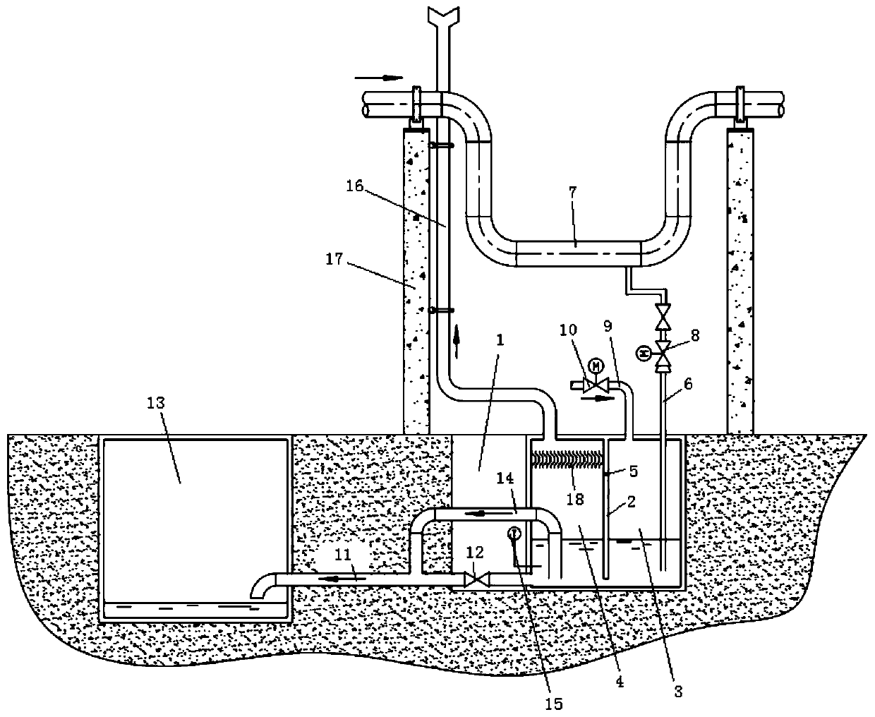
[0035] This embodiment discloses a working method of a steam pipeline drainage collection system:

[0036] Open the third valve, inject a set amount of cooling water into the chamber in advance through the cooling pipe, the cooling water level is higher than the bottom of the drain pipe, and slightly lower than the height of the highest point of the overflow pipe, and then close the third valve. When the steam pipeline in the factory area needs to be drained, open the second valve, and the drain pipe will lead the high-temperature drain into the mixed temperature chamber to mix with the cooling water in the mixed temperature chamber to cool it down. The mixed water with lower temperature flows into the discharge chamber through the gap between the partition and the bottom surface of the chamber, mixes with the cooling water in the discharge chamber again, and cools down again. When the liquid level of the mixed water in the discharge chamber exceeds the overflow pipe At the to...


PUM


Abstract

The invention relates to an environmental-friendly steam pipeline drainage collection system and a working method. The environmental-friendly steam pipeline drainage collection system comprises a warehouse chamber for being arranged underground and capable of allowing the cooling water t be injected, a partition plate is arranged in the warehouse chamber, the warehouse chamber is divided into a mixed temperature warehouse and a draining warehouse by the partition plate, the mixed temperature warehouse and the draining warehouse communicate with the gaps in the bottom faces of the warehouses through the partition plate respectively, at least one drainage pipe is connected with the mixed temperature warehouse and used for being connected with the drainage point of a steam pipeline, the drainage pipe can guide the drainage in the steam pipeline into the mixed temperature warehouse, the draining warehouse is connected with a blowdown well through an inverted-U-shaped overflow pipe, the water in the draining warehouse can be drained into the blowdown well, an emptying pipe extending beyond the ground at the set height is further connected with the draining warehouse, and the emptying pipe is used for exhausting the excess fog in the draining warehouse. The environmental-friendly steam pipeline drainage collection system can be arranged in place, the scope of the application is wide,and the safety and environment of the plant can be ensured.

Description

technical field [0001] The invention relates to the technical field of drainage equipment, in particular to an environment-friendly steam pipeline drainage collection system and a working method. Background technique [0002] The steam pipeline drainage in power plants is generally connected to the boiler atmospheric drainage expansion vessel or the steam turbine condenser expansion vessel. The inventors found that the pipelines in the factory area are generally far away from these two devices, and the drainage position of some low-level drainage is too low to meet the basic high-level requirements. Poor requirements, if these drains are directly discharged to the ground, it will cause water accumulation in summer and freezing in winter, affecting the environmental sanitation and appearance of the factory area, and high-temperature drains may cause burns to passers-by, burying safety hazards, if If it is directly discharged into rainwater wells or living water wells, the hig...

Claims


Application Information

Patent Timeline
Patent Type & Authority Applications(China)
IPC IPC(8): F17D1/06F17D3/14
CPCF17D1/06F17D3/14
Inventor 姬锋军刘嘉楷高振宝张书迎苗井泉张涛苏伟李延雷禹立坚杜银娟
Owner SHANDONG ELECTRIC POWER ENG CONSULTING INST CORP
Learn More