Deepwater pipe culvert anti-floating control system

A technology for control systems and deep water pipes, which is applied to the bottom layer of roads, protection devices, buildings, etc., can solve problems such as uneven stress on pipes and culverts, high construction costs, uneven settlement, etc., and achieve fast construction, enhanced overall strength, and structural integrity. simple effect

Pending Publication Date: 2019-08-02
CHONGQING JIAOTONG UNIVERSITY
View PDF8 Cites 0 Cited by
  • Summary
  • Abstract
  • Description
  • Claims
  • Application Information

AI Technical Summary

Problems solved by technology

Most of the pressing blocks above the pipe culverts are plain concrete squares or special-shaped squares, which may easily cause uneven force on the pipe culvert in the longitudinal direction and uneven settlement, resulting in damage to the pipe culvert
If large-scale pressure treatment is carried out on long-distance pipelines, it will bring extremely high construction costs

Method used


Image

  • Deepwater pipe culvert anti-floating control system
  • Deepwater pipe culvert anti-floating control system

Examples


Embodiment 1

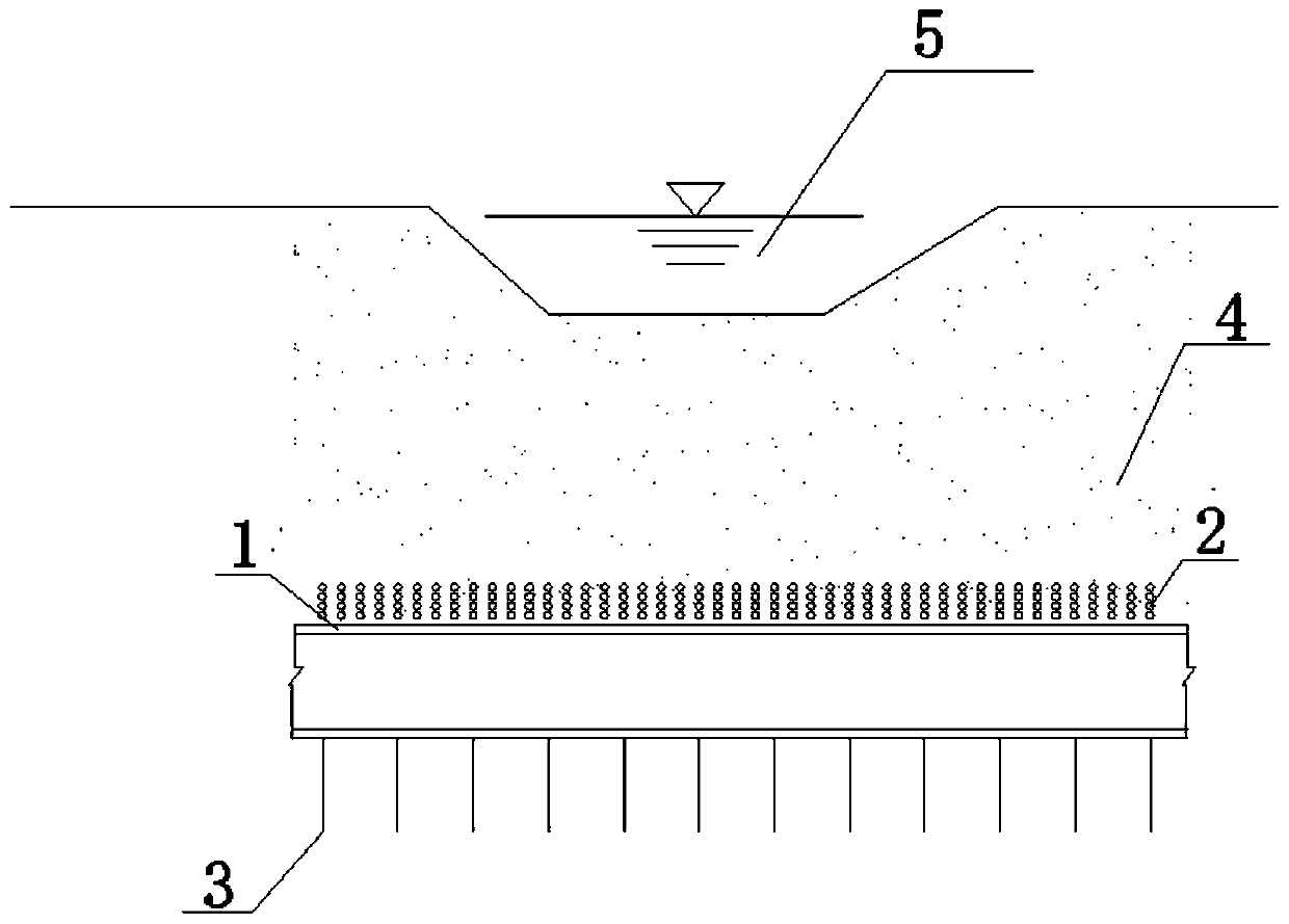
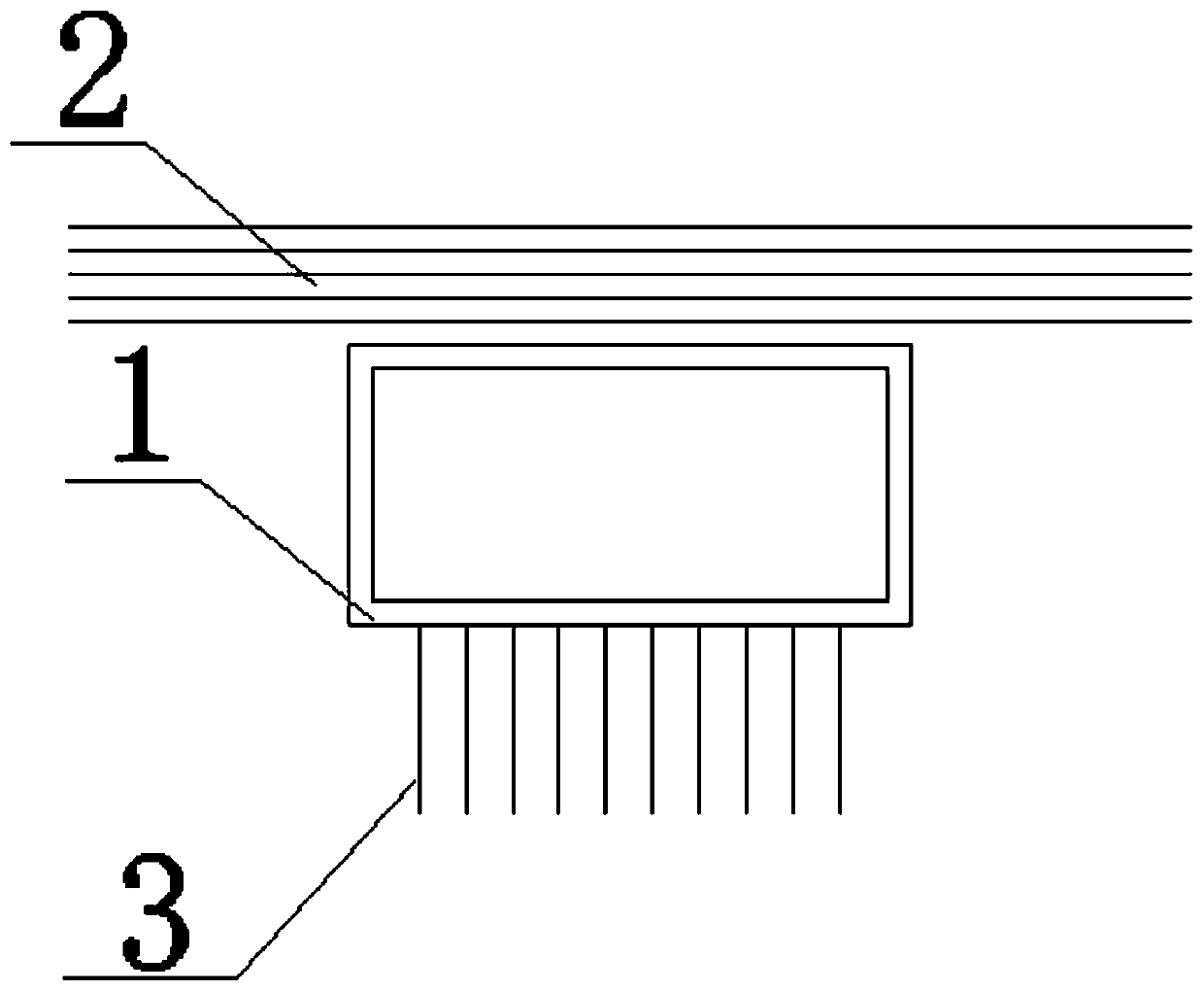
[0019] The deep-water pipe culvert anti-floating system provided in this embodiment is mainly applied to pipe culverts located in large water depths and large water level variations. This embodiment discloses an anti-floating control system for deep water pipe culverts, including pipe culverts 1 , tendons 2 and anchor rods 3 .

[0020] see figure 1 and figure 2 , the pipe culvert 1 passes through the river 5. The pipe culvert 1 is embedded in a sandstone grouting foundation or a rock formation foundation. The pipe culvert 1 is covered with a soil filling layer 4 . Several ribs 2 are arranged in the soil filling layer 4 . The length direction of the ribs 2 is perpendicular to the length direction of the pipe culvert 1 . Several anchor rods 3 are arranged under the pipe culvert 1 . The upper end of the anchor rod 3 is connected to the pipe culvert 1, and the lower end is anchored into the sandstone grouting foundation or rock formation foundation. The pipe culvert 1 gene...


PUM


Abstract

The invention provides a deepwater pipe culvert anti-floating control system. The anti-floating control system comprises a pipe culvert, ribs and anchor rods. The pipe culvert is buried in a gravel foundation or a rock foundation. The pipe culvert is covered with a soil body packing layer. The multiple ribs are arranged in the soil body packing layer. The length direction of the ribs is perpendicular to the length direction of the pipe culvert. The multiple anchor rods are arranged below the pipe culvert. The upper ends of the anchor rods are connected with the pipe culvert, and the lower endsof the anchor rods are anchored into the gravel foundation or the rock foundation. The anti-floating control system is simple in structure, practical, quick to construct and capable of saving buryingcost and effectively stopping the pipe culvert from floating up.

Description

technical field [0001] The invention relates, in particular, to an anti-floating control system for deep water pipe culverts. Background technique [0002] The floating of the pipeline is generally caused by the insufficient floating resistance provided by the overlying soil and counterweight under the buoyancy of water or saturated fluid plastic soft soil. The other type is that the pipeline produces high axial force stress under the action of factors such as internal pressure and temperature rise, which causes the pipeline to buckle and become unstable in the axial direction. Since the buried depth of the pipeline is generally shallow, its upward restraining force is small, and the axial buckling instability usually finally manifests as upward buckling, that is, floating up. [0003] In the prior art, most anti-floating engineering measures for pipe culverts are to load pressure blocks above the pipe culvert or set uplift piles below the lower pipe culvert. However, the ...

Claims


Application Information

Patent Timeline
Patent Type & Authority Applications(China)
IPC IPC(8): E01F5/00E02D31/12
CPCE01F5/005E02D31/12
Inventor 刘明维连坦帅阿比尔的梁越吴林健王俊杰
Owner CHONGQING JIAOTONG UNIVERSITY
Why Eureka
Try Eureka