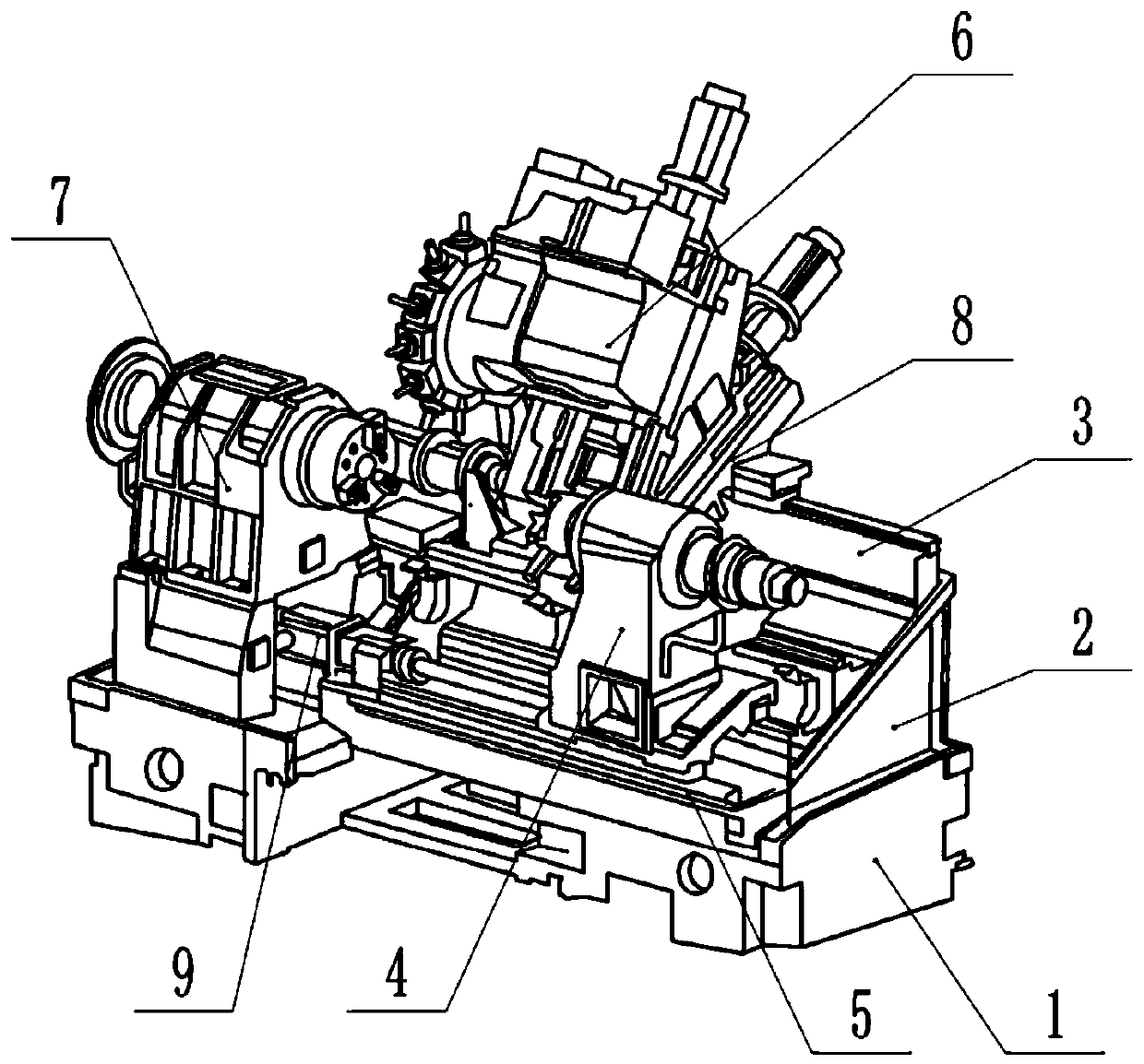
a special machine tool
A special machine tool and bed saddle technology, which is applied in metal processing machinery parts, metal processing equipment, maintenance and safety accessories, etc., can solve the problems that affect the processing accuracy, shorten the service life of guide rails, and are difficult to clean, so as to ensure the quality of processing Accuracy, improved processing accuracy, simple production and processing
- Summary
- Abstract
- Description
- Claims
- Application Information
AI Technical Summary
Problems solved by technology
Method used
Image
Examples
Embodiment 1
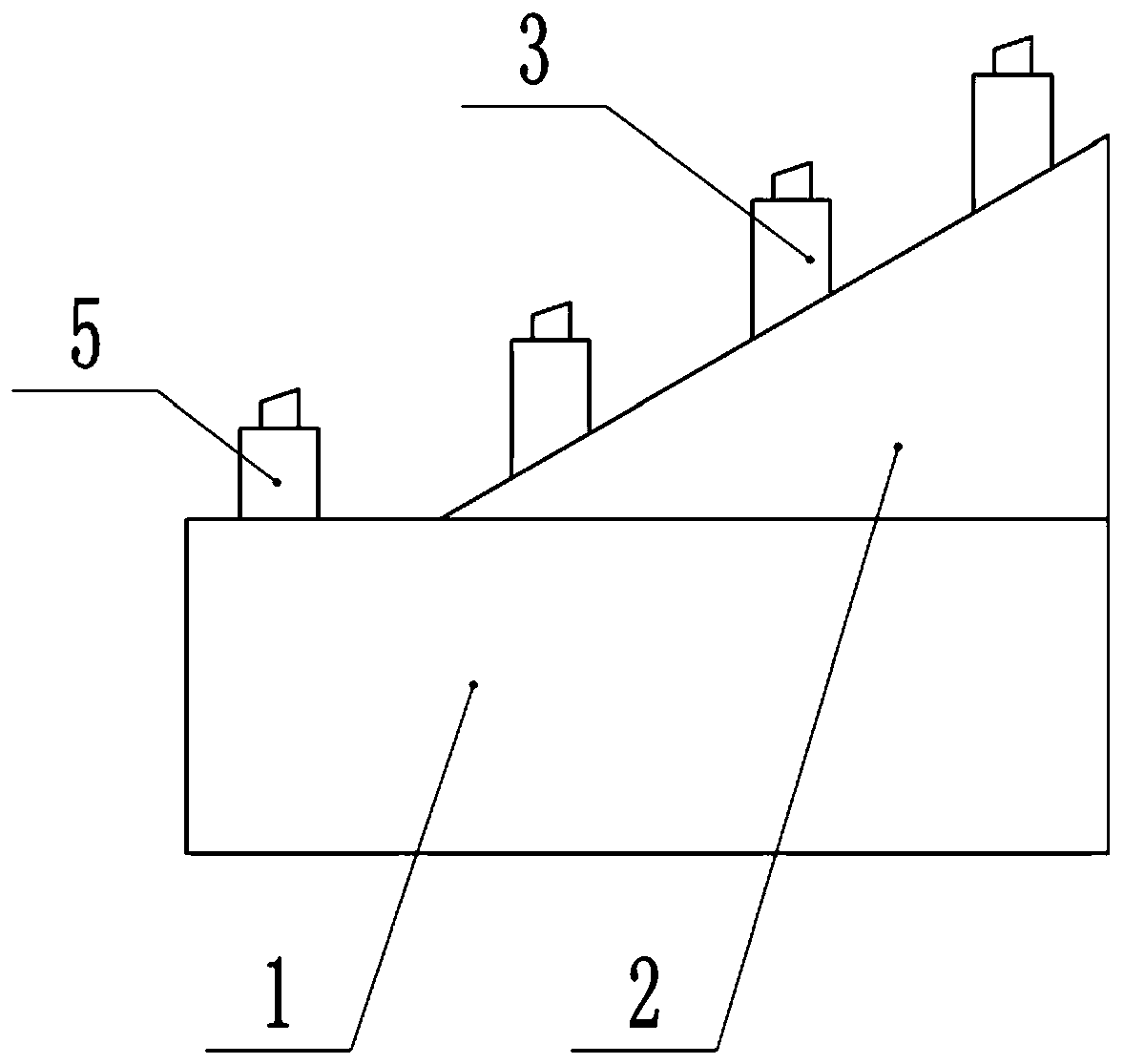
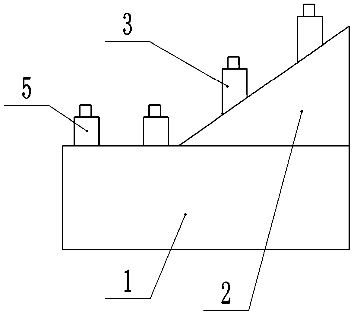
[0030] A special-purpose machine tool, comprising a base 1, an inclined bed 2, a tailstock guide rail 5, a saddle guide rail 3, a tailstock assembly 4 and a saddle assembly 8, the inclined bed 2 is fixed on the base 1 by screws, and the top of the base 1 It is a plane and parallel to the horizontal plane, and the base 1 is provided with a spindle assembly 7 . combine image 3 As shown, the saddle guide rail 3 is located on the inclined bed 2, the tailstock guide rail 5 is located on the base 1, and the top surface of the tailstock guide rail 5 and the top surface of the saddle guide rail 3 are parallel to the top surface of the base 1; The tops of the seat guide rails 5 are at the same height from the top of the base 1 , so the tops of the two tailstock guide rails 5 are on the same plane and parallel to the top surface of the base 1 . The saddle assembly 8 is slidably connected to the saddle guide rail 3, and the tailstock assembly 4 is slidably connected to the tailstock gu...
Embodiment 2
[0036] combine image 3 As shown, the cleaning assembly in this embodiment includes two sides of tailstock guide rail 5 Figure 4 The rotating disk 10 in the middle, the rotating disk 10 rolls on the base 1 along the length direction of the tailstock guide rail 5, a rotating shaft is connected between the two rotating disks 10, and the two ends of the rotating shaft pass through the rotating disk 10 and are welded on the rotating disk 10 On the inner wall far away from the tailstock guide rail 5, a bearing 19 is provided on the rotating shaft. Specifically, the bearing 19 is set in the middle of the rotating shaft, and the inner ring of the bearing 19 is welded to the rotating shaft; of course, the bearing 19 here can also be directly replaced by a sleeve Set on the sleeve on the shaft. combine Figure 5 As shown, the cleaning assembly also includes a driving block 20, the driving block 20 is slidably connected to the base 1 through the cooperation of the sliding groove and ...
Embodiment 3
[0043] In this embodiment, the rotating disk 10 is provided with several openings on the side away from the tailstock guide rail 5, and a cover is provided on the openings. When the iron filings in the cavity are almost collected, the cover can be taken out, the opening is opened, and the iron Chips are automatically discharged from the opening, thereby realizing the discharge of iron filings. Of course, the cavity is detachably connected with a magnet bar. If there is a groove on the inner wall of the cavity, insert the magnet bar in the groove, and the magnet bar can collect the iron filings in the cavity. When the iron filings are full, , open the cover, and take out the magnet bar from the opening, so as to realize taking out the iron filings from the cavity.
PUM
 Abstract
Description
Claims
Application Information
 - R&D
- Intellectual Property
- Life Sciences
- Materials
- Tech Scout
- Unparalleled Data Quality
- Higher Quality Content
- 60% Fewer Hallucinations
Browse by: Latest US Patents, China's latest patents, Technical Efficacy Thesaurus, Application Domain, Technology Topic, Popular Technical Reports.
© 2025 PatSnap. All rights reserved.Legal|Privacy policy|Modern Slavery Act Transparency Statement|Sitemap|About US| Contact US: help@patsnap.com


