
Double-fed type electrically excited synchronous motor

A synchronous motor and electric excitation technology, which is applied to synchronous motors, electrical components, and electromechanical devices for single-phase currents, can solve problems such as low torque density, reduce thermal load, improve flexibility, and reduce cooling hardware The effect of equipment requirements

Active Publication Date: 2019-07-30
ZHEJIANG UNIV
View PDF7 Cites 3 Cited by
  • Summary
  • Abstract
  • Description
  • Claims
  • Application Information

AI Technical Summary

Problems solved by technology

[0005] As mentioned above, one of the disadvantages of doubly salient electric excitation synchronous motors is its relatively low torque density. If the torque density can be further improved while maintaining its existing advantages, the competitiveness of this type of motor will be greatly increased.

Method used


Image

  • Double-fed type electrically excited synchronous motor
  • Double-fed type electrically excited synchronous motor
  • Double-fed type electrically excited synchronous motor

Examples


Embodiment 1

[0046] This embodiment mainly introduces the situation that the primary iron core is composed of several primary iron core blocks along the circumferential direction.

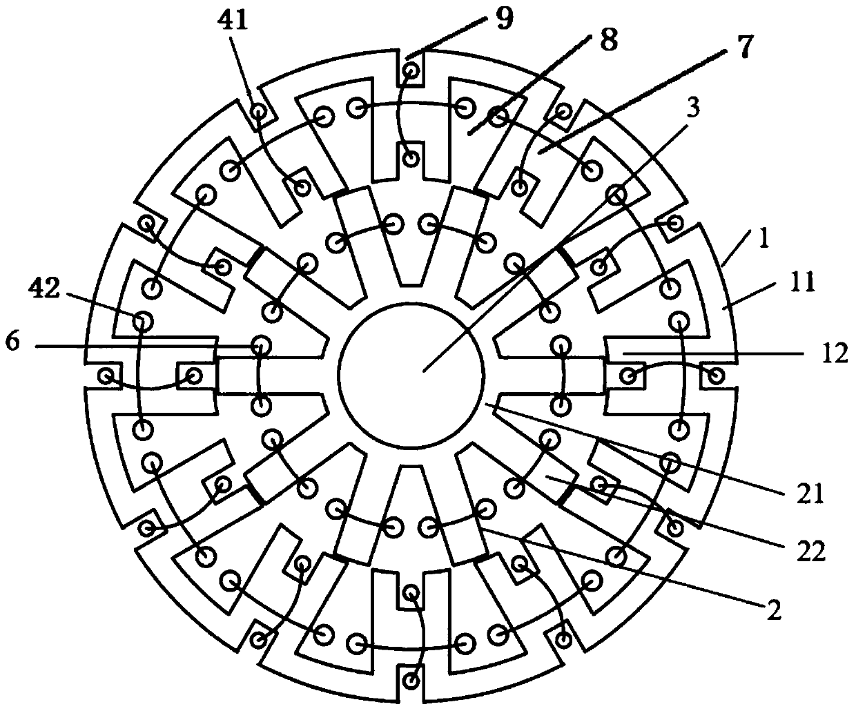
[0047] Such as figure 1 As shown, it is a double-fed electric excitation synchronous motor with primary twelve slots / secondary ten slots, including primary, secondary and shaft 3: the primary is located outside the secondary; the secondary is fixed on shaft 3; the primary includes the primary Iron core 1, excitation winding 41 and primary armature winding 42; wherein, primary iron core 1 is made up of twelve primary iron core blocks, and two adjacent primary iron core blocks are connected by magnetic bridge 7; each A primary iron core block includes a primary iron core yoke 11 and a primary iron core tooth 12;

[0048] The first primary iron core slot 8 and the second primary iron core slot 9 are formed between the primary iron core teeth 12, wherein the first primary iron core slot 8 refers to the slot inside...

Embodiment 2

[0063] Unlike the primary iron core 1 in Embodiment 1 which is a block-combined structure, this embodiment mainly introduces the case where the primary iron core has an integrated structure.

[0064] Such as Figure 7 As shown, it is a doubly-fed electric excitation synchronous motor with primary six slots / secondary four slots,

[0065] In this solution, the primary winding 4 serves both as an excitation winding and as an armature winding. The primary winding 4 adopts a double-layer centralized armature winding, and the secondary winding 6 adopts a single-layer distributed armature winding. The two sides of the primary coil are placed in two adjacent primary core slots, the secondary slots where the two sides of the secondary coil are located are two teeth apart, one secondary slot, and two primary coils separated by half a circle in series to form a primary winding of one phase. In this solution, the secondary is the rotating part, and the secondary winding 6 is connected t...


PUM


Abstract

The invention discloses a double-fed type electrically excited synchronous motor. The double-fed type electrically excited synchronous motor comprises a primary unit and a secondary unit which are both of salient pole structures; the primary unit comprises a primary iron core and a primary winding; the primary iron core comprises primary iron core teeth and a primary iron core yoke; the primary winding is arranged in a primary iron core groove formed between the primary iron core teeth; the primary winding comprises an excitation winding and an armature winding; the secondary unit comprises asecondary iron core; the secondary iron core comprises secondary iron core teeth and a secondary iron core yoke; the secondary unit further comprises a secondary winding; the secondary winding is arranged in a secondary iron core groove formed between the secondary iron core teeth; and the secondary winding comprises a secondary armature winding. According to the double-fed type electrically excited synchronous motor, on the basis that the size of an original motor is not changed, an excitation magnetic field is generated through the excitation winding, and the rotor groove space of the motoris fully utilized for mounting the secondary winding, so that the motor is provided with the primary winding and the secondary winding, and the power density and the regulation and control flexibilityof the motor are improved.

Description

technical field [0001] The invention relates to the technical field of motors, in particular to a doubly-fed electric excitation synchronous motor. Background technique [0002] In recent years, the research and development of doubly salient synchronous motors is in a rapid development stage. Compared with other types of motors, doubly salient synchronous motors have the advantages of simple structure and strong reliability. Among them, the doubly salient permanent magnet synchronous motor with a strong excitation source has a significant advantage of high power density, but due to the high price of rare earth permanent magnets, the manufacturing cost of the doubly salient permanent magnet synchronous motor remains high. Relatively speaking, it is a more economical choice to replace permanent magnet materials with traditional electric excitation. In addition, electric excitation can achieve flexible control of magnetic field strength and direction, and there is no risk of i...

Claims


Application Information

Patent Timeline
Patent Type & Authority Applications(China)
IPC IPC(8): H02K19/02H02K3/18H02K11/20H02K11/30
CPCH02K3/18H02K19/02H02K11/20H02K11/30
Inventor 吴立建方攸同王文婷方立闻汇
Owner ZHEJIANG UNIV
Learn More