Al technical title is built by PatSnap Al team. It summarizes the technical point description of the patent document.
A technology of power relay and withstand voltage, which is applied in the direction of relays, electromagnetic relays, detailed information of electromagnetic relays, etc., can solve problems affecting the comprehensive performance of withstand voltage performance, product over-travel variation, relay failure and burning, etc., to improve insulation and The effects of pressure resistance, long product life and sensitive action
Pending Publication Date: 2019-07-30
YUEQING MEISHUO ELECTRIC
View PDF0 Cites 1 Cited by
Summary
Abstract
Description
Claims
Application Information
AI Technical Summary
This helps you quickly interpret patents by identifying the three key elements:
Problems solved by technology
Method used
Benefits of technology
Problems solved by technology
[0003] In the actual work of the traditional power relay, the armature or the yoke is prone to fall off, resulting in a shortened life of the relay. In addition, in harsh environments such as vibration or when the working voltage is too high, the reed is easy to deform, especially when it is often used. There is no limit for the open static spring, and it is more prone to deformation, which leads to the over-travel variation of the product and causes the relay to fail and burn.
With the development of miniaturization of power relays, the space structure is limited, the creepage distance is short, and the withstand voltage value is not high, which affects the withstand voltage performance and other comprehensive performance of the product
Method used
Image
Click on the blue label to locate the original text in one second.
Reading with bidirectional positioning of images and text.
Examples
Embodiment Construction
[0025] The stable voltage-resistant power relay provided in this embodiment has the advantages of compact structure, small size, excellent insulation performance, high voltage resistance, high stability, and long service life of the product, and is simple in structure, easy to process and realize automatic assembly.
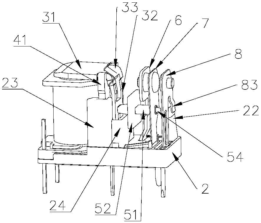
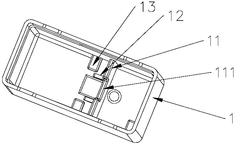
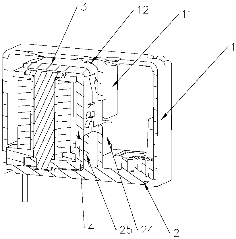
[0026] Such as figure 1 , figure 2 As shown, the power relay with stable voltage resistance provided by this embodiment includes a case 1, a base 2, an armature 3, a yoke 4, a push rod 5, a normally closed static spring 6, a normally open static spring 8 and a moving spring 7 , wherein the armature 3 and the yoke 4 are connected together by the shrapnel, the yoke 4 is inserted into the mounting groove 23 of the base 2, the lower part of the side walls of the two mounting grooves 23 is connected with the rectangular pressure-resistant groove 24, and the 3 armatures 32 are vertically The tail part of the section fits with the pressure-resistant groove 24 in a gap...
PUM
Abstract
The invention discloses a stable and voltage-resistant power relay. The power relay comprises a casing, a base, an armature, a yoke, a pushrod, a normally-closed static spring, a normally-open staticspring and a dynamic spring, wherein the armature and the yoke are connected together through an elastic sheet, the yoke is installed on the base in an inserted mode, limit blocks at the bottom of thecasing prevents the yoke from shifting upwards, a baffle in the casing avoids lateral shift of the armature, arc-shaped stop blocks avoid upward shift of the armature, the tail of the armature and avoltage-resistant slot of the base are in clearance fit, the tail of the armature is connected with one end of the pushrod through a connecting hole, the other end of the pushrod is connected with a connecting hole of the dynamic spring, an insulation screen is arranged in the middle of the pushrod, the creepage distance between the dynamic spring and the armature is prolonged, the normally-open static spring with a buffer sheet is inserted into the base, a trapezoidal protective plate of the base is in fit with the buffer sheet, and limit protection of the normally-open static spring is realized. The stable and voltage-resistant power relay has the advantages of being compact in structure, small in size, excellent in insulating property, resistant to voltage, high in stability, long in product service life and the like; and moreover, the structure is simple, and it is convenient to perform processing and realize automatic assembling.
Description
technical field [0001] The invention relates to a small electromagnetic relay, in particular to a power relay with stable voltage resistance, and belongs to the technical field of electrical equipment. Background technique [0002] Electromagnetic relay is a relay that uses electromagnetic force to drive the relative movement of mechanical parts to produce a predetermined response. It is generally composed of iron core, coil, armature, yoke, dynamic and static reed with contacts, etc. When the current passes through the coil, an electromagnetic force is generated, and the armature is attracted, so that the moving contact of the moving reed is in contact with the static contact of the static reed; when the current in the coil disappears, the electromagnetic force disappears, and the armature resets, thus The moving contact of the moving reed is separated from the static contact of the static reed, and the purpose of conducting or cutting off the circuit is achieved through th...
Claims
Application Information
Patent Timeline
Application Date:The date an application was filed.
Publication Date:The date a patent or application was officially published.
First Publication Date:The earliest publication date of a patent with the same application number.
Issue Date:Publication date of the patent grant document.
PCT Entry Date:The Entry date of PCT National Phase.
Estimated Expiry Date:The statutory expiry date of a patent right according to the Patent Law, and it is the longest term of protection that the patent right can achieve without the termination of the patent right due to other reasons(Term extension factor has been taken into account ).
Invalid Date:Actual expiry date is based on effective date or publication date of legal transaction data of invalid patent.