
Front gas and liquid separation vacuum maintaining device

A gas-liquid separation and separation device technology, applied in separation methods, dispersed particle separation, non-displacement pumps, etc., can solve problems such as affecting the working state and service life of vacuum pumps, low heat exchange efficiency on the cooling water side, and inconvenient on-site layout. , to ensure the working state and service life, the structure is simple, the effect of reducing the workload

Pending Publication Date: 2019-07-30
WUHAN WU PUMP PUMP MFG
View PDF0 Cites 0 Cited by
  • Summary
  • Abstract
  • Description
  • Claims
  • Application Information

AI Technical Summary

Problems solved by technology

Furthermore, vacuum pumps generally cannot directly inhale air (non-condensable gas) mixed with water vapor. Higher temperature water vapor will affect the working state and service life of the vacuum pump.
[0003] However, the existing vacuum suction devices generally have problems such as complex structure, low heat transfer efficiency on the cooling water side, large footprint and inconvenient on-site layout.

Method used


Image

  • Front gas and liquid separation vacuum maintaining device

Examples


Embodiment Construction

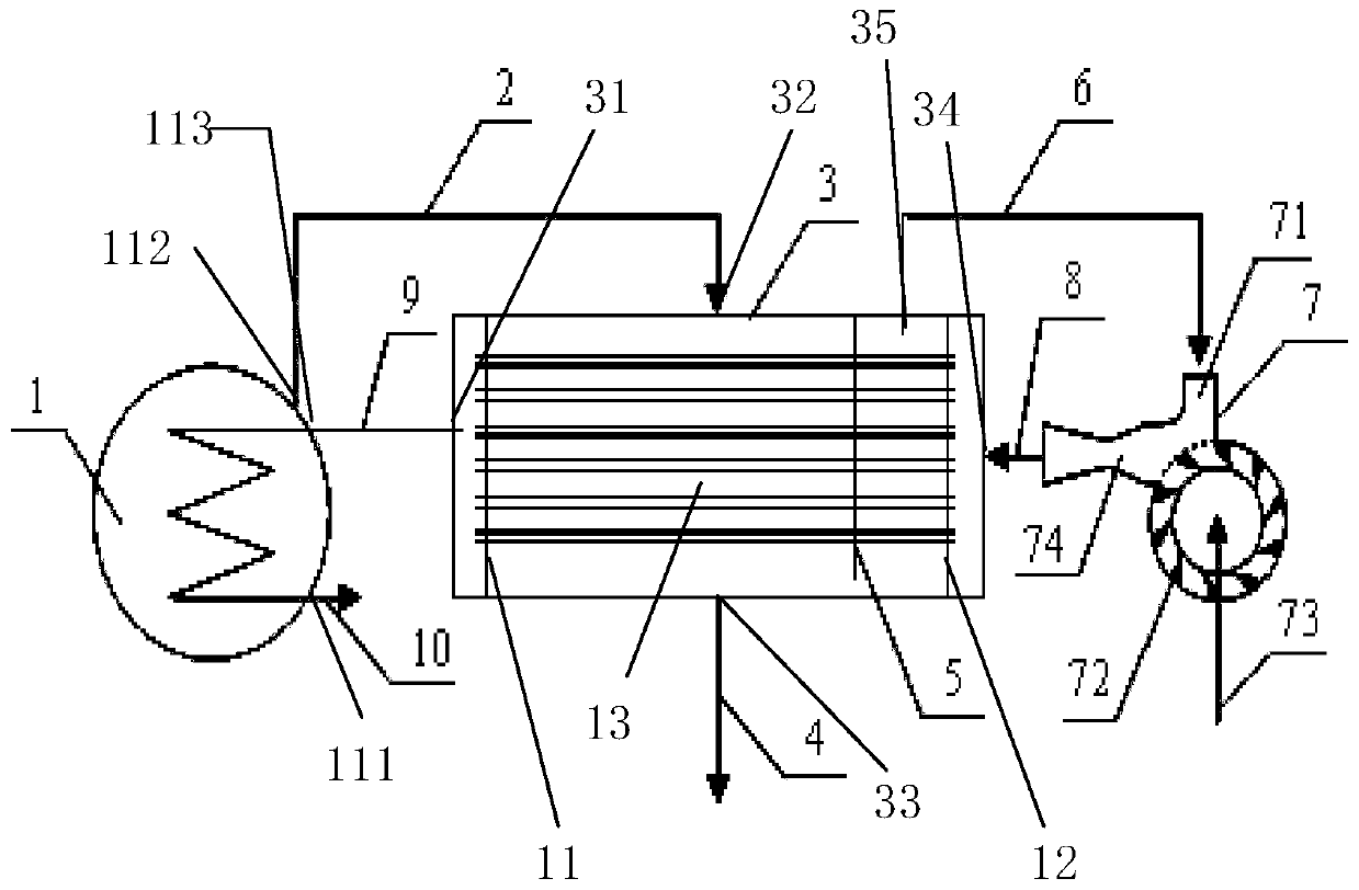
[0027] The following is attached figure 1 The principles and features of the present invention are described, and the examples given are only used to explain the present invention, and are not used to limit the scope of the present invention. In the following paragraphs the invention is described more specifically by way of example with reference to the accompanying drawings. Advantages and features of the present invention will be apparent from the following description and claims. It should be noted that all the drawings are in a very simplified form and use imprecise scales, and are only used to facilitate and clearly assist the purpose of illustrating the embodiments of the present invention.

[0028] It should be noted that when a component is said to be "fixed" to another component, it can be directly on the other component or there can also be an intervening component. When a component is said to be "connected" to another component, it may be directly connected to the...


PUM


Abstract

The invention relates to a front gas and liquid separating vacuum maintaining device. The device is simple in structure, small in floor size and capable of being arranged on site; a first partition plate and a second partition plate are arranged inside a steam-gas separating device, the internal space of the steam-gas separating device is partitioned into three cabins through the first partition plate and the second partition plate, the cabins are the working water outlet cabin, the heat exchange cabin and the working water inlet cabin from left to right in sequence, and working water enters the working water inlet cabin from a second water inlet in the right side of the steam-gas separating device, and flows through a heat exchange tube to perform heat exchange with non-condensable gas with high temperature inside the heat exchange cabin; working water flows through the heat exchange tube to perform heat exchange inside the heat exchange cabin, due to the fact that the heat exchange tube is arranged horizontally, the heat exchange efficiency with the non-condensable gas is high, the cooling efficiency of the non-condensable gas is high, the working efficiency of a vacuum pump is improved, and the working state and the service life of the vacuum maintaining device are ensured.

Description

technical field [0001] The invention relates to a vacuum maintaining device, in particular to a pre-gas-liquid separation vacuum maintaining device. Background technique [0002] Whether it is large-scale energy power generation industries such as thermal power and nuclear power, or chemical processes such as steel and medicine, condensers are involved, and condensers have become one of the main equipment in the chemical industry. The condenser generally operates in a high vacuum state. Due to the inevitable air leakage of industrial equipment, the condensed steam is mixed with more air during the condensation process. If the leaked air not only affects the condensation heat transfer efficiency, but also the increasing air will Destroying the vacuum degree of the condenser makes the chemical engineering deviate from the design value, and the efficiency / production capacity decreases, which directly affects the economics of the process. In actual industrial production, in ord...

Claims


Application Information

Patent Timeline
IPC IPC(8): B01D53/00F04F5/04
CPCB01D53/002F04F5/04
Inventor 王静张怀明
Owner WUHAN WU PUMP PUMP MFG
Learn More