Position storage device, position reading device and position reading method
A storage device and reading device technology, which is applied to record carriers, instruments, and inductive record carriers used by machines, can solve the problems of easy loss of stored information, poor environmental compatibility, single reading point, etc., and achieve long service life. , prolong the service life, the effect of location information storage security
- Summary
- Abstract
- Description
- Claims
- Application Information
AI Technical Summary
Problems solved by technology
Method used
Image

Examples
Embodiment 1
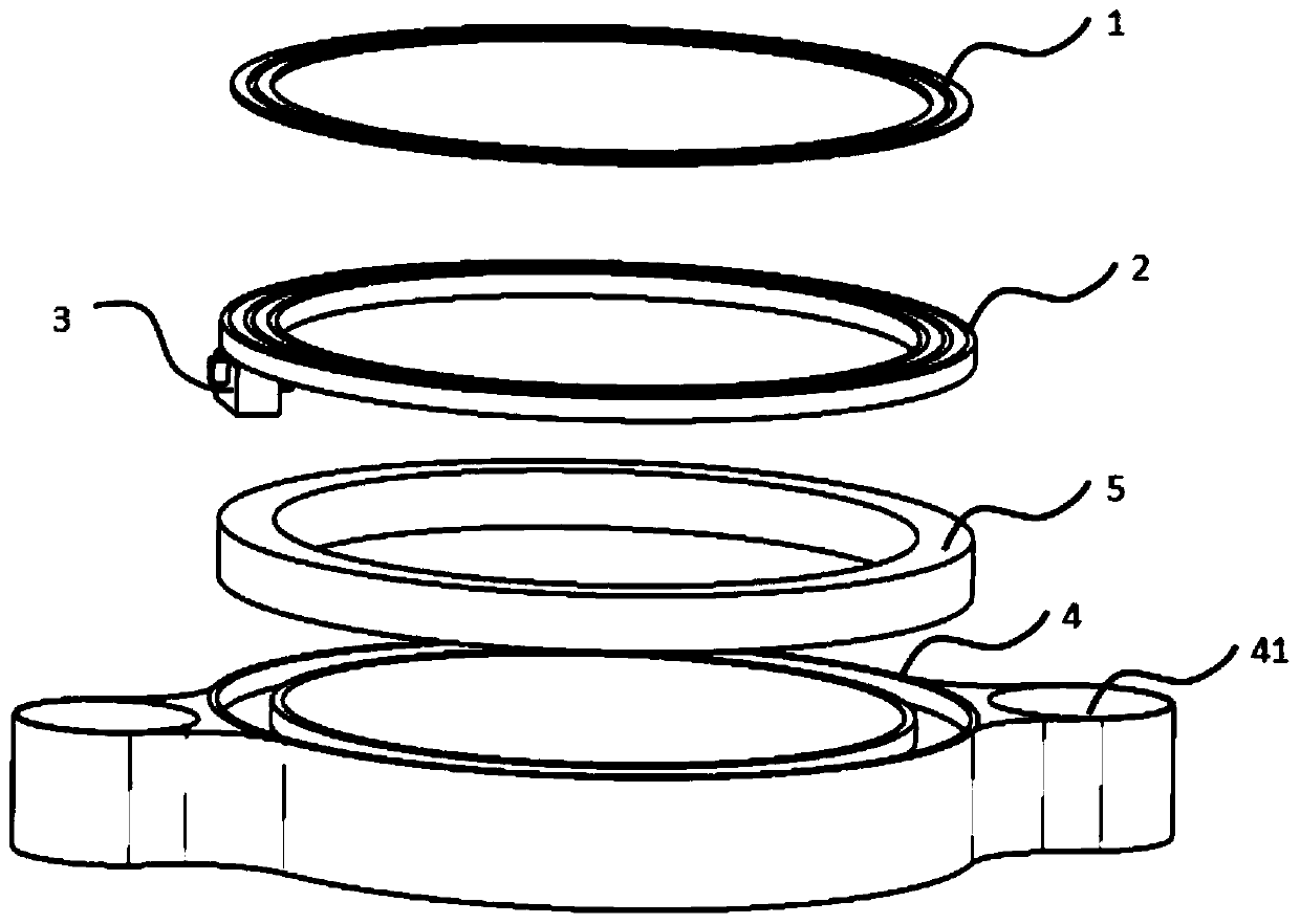
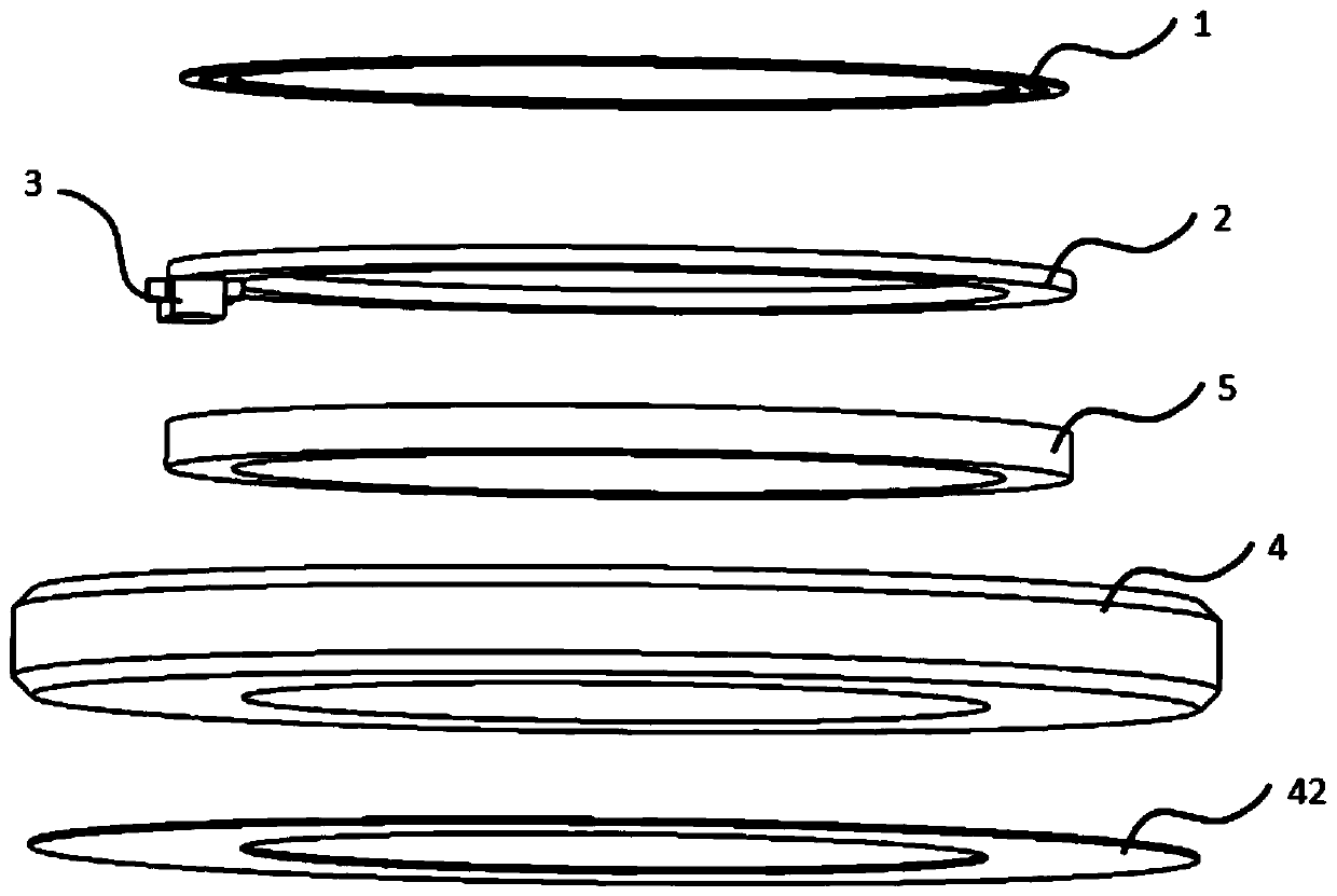
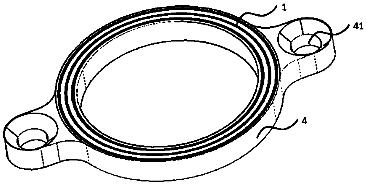
[0056] See Figure 1-2 , This embodiment provides a position storage device, including: a contact layer 1, a circuit layer 2, a base layer 4;
[0057] The contact layer 1 is laid on the surface of the circuit layer 2, and the contact layer 1 is used for communicative contact connection with external equipment;
[0058] One side of the circuit layer 2 is provided with a memory chip 3, the memory chip 3 is used to store position information and clocks, and one side of the contact layer 1 is communicatively connected with the memory chip 3;
[0059] The circuit layer 2 is fixed to the base layer 4, and the base layer 4 is used to protect the fixed circuit layer 2; among them, the memory chip 3 is a passive memory chip 3.
[0060] Now this embodiment will be specifically described in detail:
[0061] Specifically, this embodiment is mainly suitable for identifying the position of the measuring point during measuring tool measurement, and making the position correspond to the measurement res...
Embodiment 2
[0091] See Figure 11-12 This embodiment provides a position reading device, which is applied to the position information reading of the position storage device required by any one of Embodiment 1. The position storage device includes a contact layer 1, a circuit layer 2, a base layer 4; The taking device includes: a telescopic contact 72, a contact carrying block 71, and a processing circuit 74;
[0092] The telescopic contact 72 is fixed to the contact bearing block 71, and the telescopic contact 72 is used for elastic contact with the contact layer 1, so as to realize the communicable connection between the position reading device and the position storage device;
[0093] The telescopic contact 72 and the processing circuit 74 may be communicatively connected. The processing circuit 74 is used to read the position information and clock stored in the position storage device, and decode the position information to obtain the position readable information.
[0094] Now this embodime...
Embodiment 3
[0102] See Figure 13 This embodiment provides a location reading method, which is applied to the location information reading of the location storage device as required in any one of Embodiment 1, and includes the following steps:
[0103] S1: The position storage device receives the reset pulse signal and sends a response pulse signal to establish a communication connection with the position storage device;
[0104] S2: The location storage device sends a location code and a check code, the location code is the location information stored in the storage device, and the check code is used to check the location code to check the correctness of the data;
[0105] S3: Initialize the location storage device to facilitate the next reading of location information.
[0106] Combine Figure 13 , Now this embodiment will be described in detail:
[0107] Figure 13 Among them, the receiving end is the position information reading end, and the storage end is the position information storage end. ...
PUM
 Abstract
Description
Claims
Application Information
 - R&D
- Intellectual Property
- Life Sciences
- Materials
- Tech Scout
- Unparalleled Data Quality
- Higher Quality Content
- 60% Fewer Hallucinations
Browse by: Latest US Patents, China's latest patents, Technical Efficacy Thesaurus, Application Domain, Technology Topic, Popular Technical Reports.
© 2025 PatSnap. All rights reserved.Legal|Privacy policy|Modern Slavery Act Transparency Statement|Sitemap|About US| Contact US: help@patsnap.com