Eureka AIR delivers breakthrough ideas for toughest innovation challenges, trusted by R&D personnel around the world.

Analog beam forming method, receiver and communication device

A technology for simulating beams and receivers, applied in the directions of space transmit diversity, radio transmission systems, electrical components, etc., it can solve the problems of reducing the ability of the receiver to receive useful signals and improving the noise figure of the receiver, so as to increase the cost and reduce the loss. Effect

Active Publication Date: 2019-07-23
HENAN POLYTECHNIC UNIV
View PDF8 Cites 3 Cited by
  • Summary
  • Abstract
  • Description
  • Claims
  • Application Information

AI Technical Summary

Problems solved by technology

[0005] However, the obvious disadvantage of the automatic gain control function is that while adjusting the receiver gain, it will reduce the ability of the receiver to receive useful signals. In other words, automatic gain control will cause the noise figure of the receiver to increase

Method used


Image

  • Analog beam forming method, receiver and communication device
  • Analog beam forming method, receiver and communication device
  • Analog beam forming method, receiver and communication device

Examples


Embodiment Construction

[0047] In order to make the purpose, technical solutions and advantages of the embodiments of the present invention more clear, the embodiments of the present invention will be further described in detail below in conjunction with the accompanying drawings. Here, the exemplary embodiments and descriptions of the present invention are used to explain the present invention, but not to limit the present invention.

[0048] Figure 4 is a schematic flowchart of an analog beamforming method according to an embodiment of the present invention. Such as Figure 4 As shown, the analog beamforming method of an embodiment may include:

[0049] Step S110: using the antenna array to receive multiple beams;

[0050] Step S120: If there is interference in the plurality of beams, determine the direction of the interference;

[0051] Step S130: applying additional weights to the antenna array according to the direction of the interference, so as to turn off the signal channel of the antenn...


PUM


Abstract

The invention provides an analog beam forming method, a receiver and a communication device, and the method comprises the steps: receiving a plurality of beams through an antenna array; under the condition that interference exists in the multiple wave beams, determining the direction where the interference is located; applying an additional weight value to the antenna array according to the direction in which the interference is located so as to switch off a signal channel of an antenna unit of at least one corner of the antenna array when the plurality of beams are gained; and combining the plurality of gained beams to obtain an analog beam. According to the scheme, the receiving gain in the direction where interference is located can be restrained, the gain loss can be reduced, meanwhile, interference signals in analog beams are reduced, cost cannot be increased, and signal delay cannot be generated.

Description

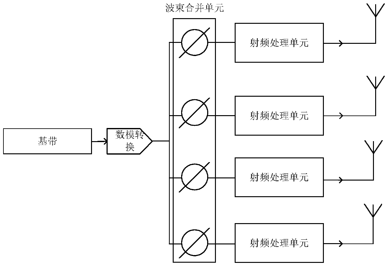
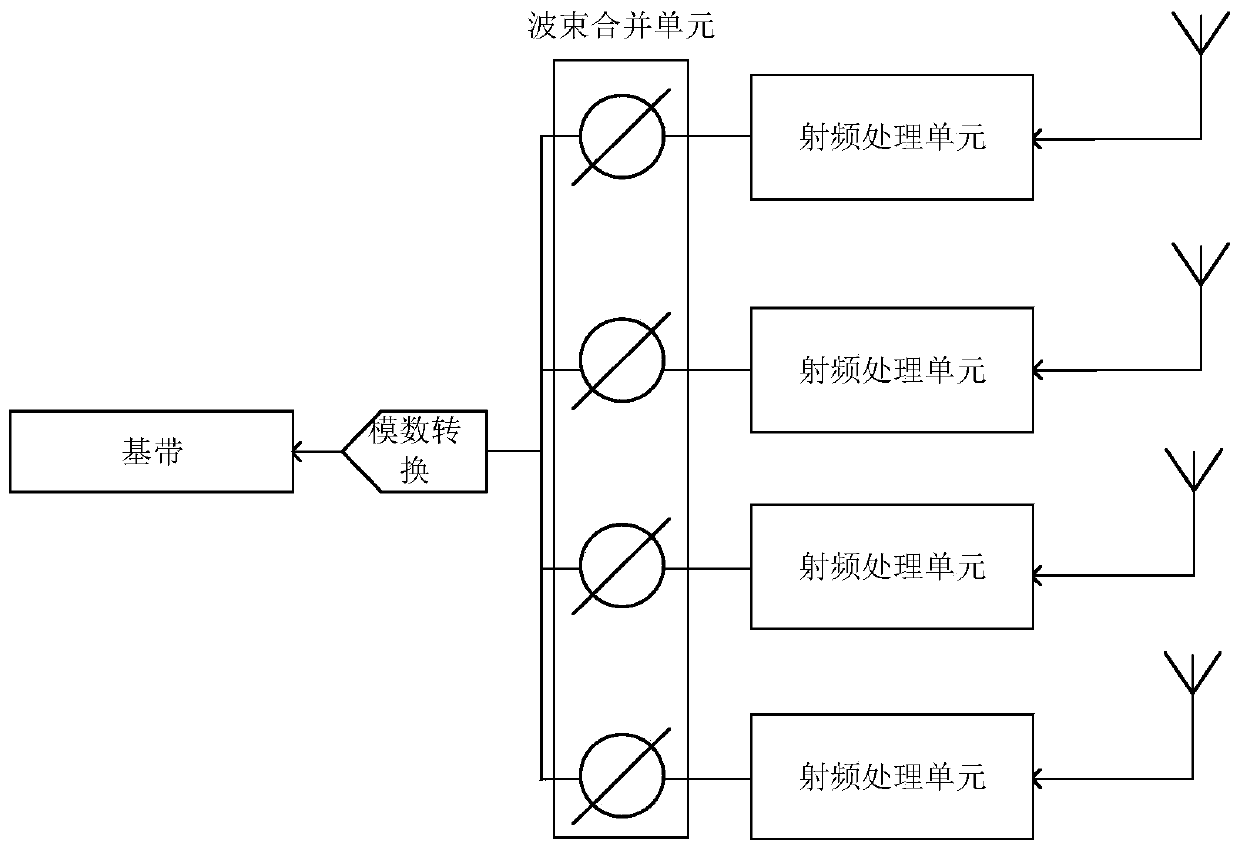
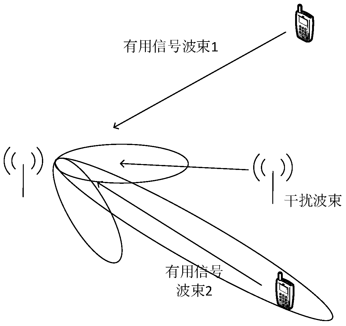
technical field [0001] The present invention relates to the technical field of wireless communication, in particular to an analog beam forming method, a receiver and a communication device. Background technique [0002] Analog beamforming typically relies on selecting a series of preset beams for transmitting and receiving data streams. The antenna array forms vertical and horizontal beams in a two-dimensional angle, and the beams can be set to form sectors or hotspots to form spatial isolation and realize user multiplexing. [0003] In the process of forming the analog beam, the antenna gain can be performed by setting weights (usually phase offsets) for the antenna units and combining the weighted antenna units. figure 1 and figure 2 They are the structural diagrams of the analog transmitter and the analog receiver respectively, combined with figure 1 and figure 2 As shown, the signals are combined after an analog phase shift. [0004] image 3 is a schematic diagr...

Claims


Application Information

Patent Timeline
Patent Type & Authority Applications(China)
IPC IPC(8): H04B7/08
CPCH04B7/086H04B7/0848
Inventor 张利伟蔡小琳古秋磊
Owner HENAN POLYTECHNIC UNIV
Why Eureka
Eureka Blog
Learn More