Arc isolation cover of circuit breaker

A circuit breaker and circuit breaker body technology, applied in the direction of circuit breaker components, etc., can solve the problems of phase-to-phase breakdown, lower insulation degree, and the influence of circuit breaker insulation protection level on the difficulty of installation, so as to prevent welding and reduce manufacturing costs. Low, to avoid the effect of phase breakdown

Pending Publication Date: 2019-07-23
CHANGSHU SWITCHGEAR MFG CO LTD (FORMER CHANGSHU SWITCHGEAR PLANT)
View PDF0 Cites 1 Cited by
  • Summary
  • Abstract
  • Description
  • Claims
  • Application Information

AI Technical Summary

Problems solved by technology

Although the arc shield made of insulating material can play a good role in eliminating ionization and improving the insulation level of the circuit breaker, but whether the structure of the arc shield is reasonable or not has a great influence on the insulation protection level of the circuit breaker and the difficulty of installation. Ease of use, etc. will have a corresponding impact
[0003] The existing technology pays more attention to the insulation between phases when the circuit breaker is equipped with an arc shield, but often neglects to pay attention to the pollution of the circuit breaker terminal and external busbar caused by the arc ejected from the arc extinguishing chamber. Significantly reduce the influence of insulation and even have risks such as interphase breakdown. The external busbars or external cables required for wiring) are in the same space where the two are not isolated

Method used


Image

  • Arc isolation cover of circuit breaker
  • Arc isolation cover of circuit breaker
  • Arc isolation cover of circuit breaker

Examples


Embodiment 1

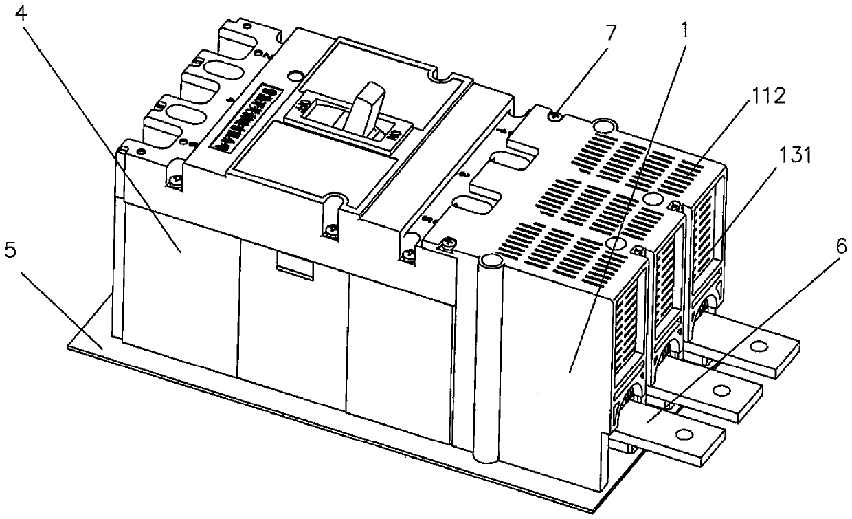
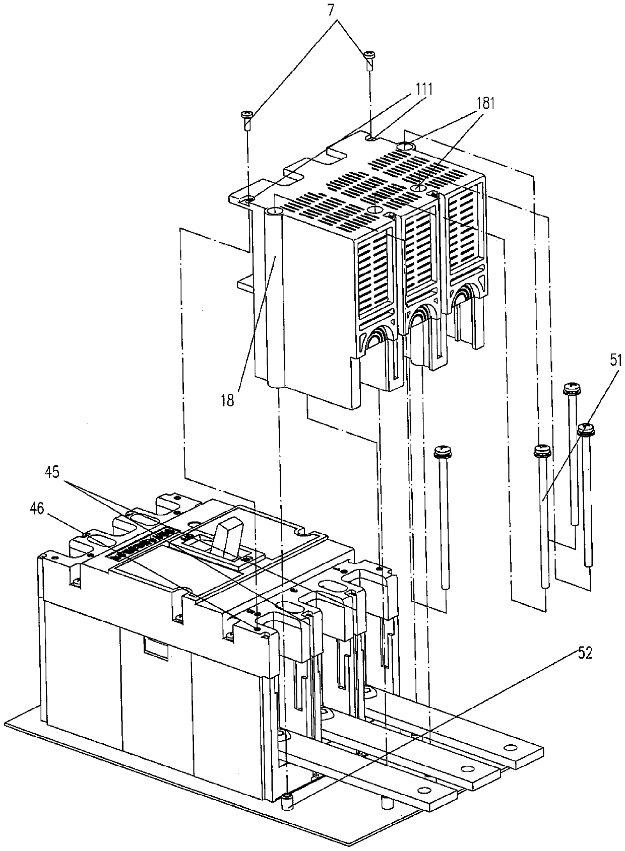
[0070] Such as Figure 1a , 1b , 1c, 4, 5a, 5b, the circuit breaker body 4 and the outer arc shield 1 are fixed on the bottom plate 5 in a state distributed from left to right, and the outer arc shield 1 includes Two side panels 12 facing each other in parallel, a top plate 11 between the upper parts of the pair of side panels 12 and a rear panel 13 away from the circuit breaker body 4, so that the outer arc shield 1 is in the shape of a parallelepiped and forms a direction toward The opening of the circuit breaker body 4 , the circuit breaker body 4 and the outer arc shield 1 are fixed on the bottom plate 5 and the opening of the outer arc shield 1 is engaged with the circuit breaker body 4 . In the outer arc shield cavity of the outer arc shield 1 and between the pair of side panels 12, interphase partitions 14 are arranged at intervals, and the phase partitions 14 are parallel to the pair of side panels 12. And the height of the phase partition 14 is adapted to the pair of...

Embodiment 2

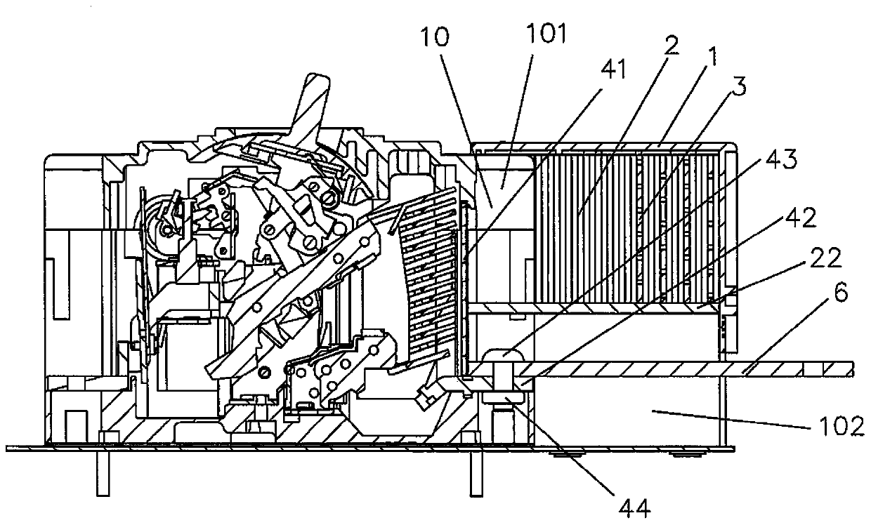
[0076] Such as Figure 6a , 6b As shown, the inner arc shield 2 described in this embodiment is inserted into each chamber 10 of the outer arc shield 1 as a single part, so its number is equal to the number of phases of the circuit breaker body 4 . The inner arc shield 2 is installed on the lower part of the outer arc shield 1, and the cross section of the inner arc shield 2 is "Π" shape, that is, the isolation insulating plate 22 is located on the top of the two side plates 21 and parallel Therefore, the upper chamber of the isolation insulating board 22 is the deionization chamber 101 , and the lower chamber is the wiring bar installation chamber 102 . The top plate 11 of the outer arc shield 1 protrudes toward the insulating insulating plate 22 with an outer arc shield reinforcing rib 113, and the outer arc shield reinforcing rib 113 extends to the inner wall of the side panel 12 or is spaced apart from each other. On the plate 14 , the strip-shaped ribs extending to the ...

Embodiment 3

[0079] Such as Figure 7a , Figure 7b As shown, the inner arc shield 2 described in this embodiment is integrally arranged and spliced ​​with the outer arc shield 1 as a whole part to form an arc shield, and the inner arc shield 2 is installed on the outer arc shield 1 the lower part. The interphase partitions 14 extend from the top plate 11 in the outer arc shield cavity of the outer arc shield 1 to an extent suitable for the height of the free space elimination chamber 101 .

[0080] The inner arc shield 2 includes two side plates 21 arranged facing each other and parallel to each other, and a partition plate 24 arranged between the two side plates 21 and adapted to the height of the terminal block installation cavity 102. Both ends of the insulating spacer 22 are connected to opposite sides of a pair of side plates 21 , and the middle of the insulating spacer 22 is connected to the top of the spacer 24 . The partitions 24 are provided with cylindrical installation ribs ...


PUM


Abstract

An arc isolation cover of a circuit breaker belongs to the technical field of low-voltage electric appliances. The circuit breaker comprises a circuit breaker body. The circuit breaker body is provided with a circuit breaker arc extinguish chamber, and the circuit breaker arc extinguish chamber is provided with a circuit breaker arc extinguish chamber air outlet. The arc isolation cover comprisesan outer arc isolation cover, and the outer arc isolation cover is provided with an outer arc isolation cover cavity. The arc isolation cover is characterized by further comprising an inner arc isolation cover, the inner arc isolation cover is arranged in the outer arc isolation cover cavity, an insulation isolation board is arranged on the inner arc isolation cover, the outer arc isolation covercavity is divided into a deionization cavity positioned above the insulation isolation board and an external bus bar cavity positioned below the insulation isolation board in the height direction by the insulation isolation board, the deionization cavity is right opposite to an air outlet of the circuit breaker arc extinguish chamber and accommodates high-temperature electric arcs sprayed out fromthe air outlet of the circuit breaker arc extinguish chamber when the circuit breaker body is disconnected, and an external connecting cable penetrates through the external bus bar cavity. The influence by the electric arcs sprayed out of the arc extinguishing chamber is prevented, interphase breakdown is avoided, the structure is simple, assembling is convenient, and economy and cheapness are realized.

Description

technical field [0001] The invention belongs to the technical field of low-voltage electrical appliances, and in particular relates to an arc shield of a circuit breaker. Background technique [0002] As known in the industry, the function of a low-voltage circuit breaker is to break or cut off the fault current. Specifically, when the moving contact of the contact system of the low-voltage circuit breaker is separated from the static contact, the fault current is broken. Furthermore, as known in the industry, when the moving contact is separated from the static contact to break the fault current, an arc will be generated in the arc extinguishing chamber and the arc will be sprayed outward from the gas outlet of the arc extinguishing chamber, because the outwardly sprayed arc will cause Problems such as phase-to-phase breakdown and ablated parts, therefore, an arc hood is usually installed outside the circuit breaker to alleviate or even avoid the aforementioned problems. A...

Claims


Application Information

Patent Timeline
Patent Type & Authority Applications(China)
IPC IPC(8): H01H73/18
CPCH01H73/18
Inventor 瞿帅强王铖顾建青
Owner CHANGSHU SWITCHGEAR MFG CO LTD (FORMER CHANGSHU SWITCHGEAR PLANT)
Why Eureka
Try Eureka