Ultra-wideband pulse signal transmitting device and ultra-wideband pulse radar system

An ultra-wideband pulse and signal transmission technology, which is applied in the direction of measuring devices, radio wave measurement systems, and re-radiation, can solve the problems of increasing system power consumption, limited effect, and high-power amplifiers, so as to reduce system power consumption Effect

Active Publication Date: 2021-03-23
西安芯屹科技有限公司
View PDF10 Cites 0 Cited by
  • Summary
  • Abstract
  • Description
  • Claims
  • Application Information

AI Technical Summary

Problems solved by technology

In order to achieve high transmit power, considering the power-added efficiency of the power amplifier, a power amplifier with very large power consumption is required, which increases the power consumption of the system
Typically, optimizing power amplifiers to improve their operating efficiency has very little effect on reducing overall system power consumption

Method used


Image

  • Ultra-wideband pulse signal transmitting device and ultra-wideband pulse radar system
  • Ultra-wideband pulse signal transmitting device and ultra-wideband pulse radar system
  • Ultra-wideband pulse signal transmitting device and ultra-wideband pulse radar system

Examples


Embodiment 1

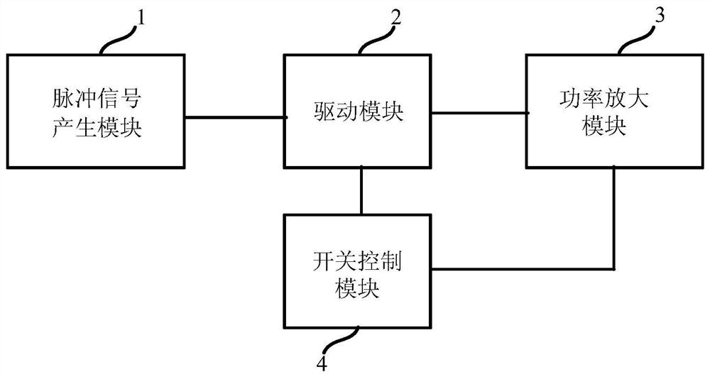
[0061] See figure 1 , figure 1 It is a block diagram of an ultra-wideband pulse signal transmitting device provided by an embodiment of the present invention. The ultra-wideband pulse signal transmitting device of the present embodiment includes a pulse signal generation module 1, a drive module 2, a power amplification module 3 and a switch control module 4, wherein the pulse signal generation module 1 is used to generate ultra-wideband pulses with a certain number of single pulses signal; the drive module 2 is used to amplify the ultra-wideband pulse signal; the power amplification module 3 is used to amplify the power of the amplified ultra-wideband pulse signal to generate a transmission signal; the switch control module 4 is used to control the drive module 2 and the power amplifying module 3 are turned off within a preset period of time.

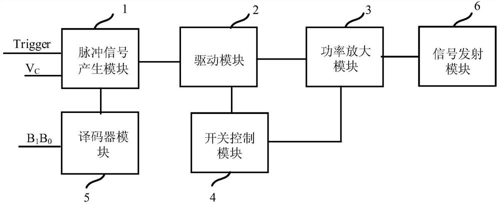
[0062] Further, see figure 2 , figure 2 It is a block diagram of another ultra-wideband pulse signal transmitting device provid...

Embodiment 2

[0071] On the basis of the above embodiments, this embodiment describes in detail the circuit structure of the ultra-wideband pulse signal transmitting device. See Figure 4 , Figure 4 It is a schematic block diagram of a pulse signal generating module provided by an embodiment of the present invention. The pulse signal generating module 1 of the present embodiment includes a delay chain submodule 11, a single pulse generation submodule 12 and a pulse combination submodule 13, wherein the delay chain submodule 11 includes N delay units 111 connected in sequence, for generating N time-delay signals; the single-pulse generation submodule 12 includes N single-pulse generation units 121 connected one-to-one with N time-delay units 111, for generating N single-pulse signals according to N time-delay signals; pulse combination The sub-module 13 is respectively connected to the output terminals of N pulse generating units 121 for splicing N single pulse signals to form an ultra-wi...


PUM


Abstract

The invention relates to an ultra-wideband pulse signal transmitting device and an ultra-wideband pulse radar system. The ultra-wideband pulse signal transmitting device comprises a pulse signal generating module, which is used for generating ultra-wideband pulse signals with a certain number of single pulses; a driving module, which is used for amplifying the ultra-wideband pulse signal; a poweramplifying module, which is used for amplifying the power of the ultra-wideband pulse signal subjected to signal amplification to generate a transmitting signal; and a switch control module, which isused for controlling the driving module and the power amplification module to be switched off in a preset time period. The ultra-wideband pulse signal transmitting device adopts an ultra-wideband pulse signal generating circuit realized by an all-digital logic circuit, and only generates transient power consumption in the working process without direct current power consumption, so that the powerconsumption of the system can be obviously reduced.

Description

technical field [0001] The invention belongs to the technical field of electronic circuits, and in particular relates to an ultra-wideband pulse signal transmitting device and an ultra-wideband pulse radar system. Background technique [0002] Ultra-wideband pulse radar is a time-domain imaging detection system that works under the nanosecond pulse system. It has a wide range of applications in the fields of short-distance high-precision ranging and positioning, non-contact medical monitoring, and wall-penetrating detection. The application of CMOS (Complementary Metal Oxide Semiconductor, Complementary Metal Oxide Semiconductor) technology can significantly reduce the size and power consumption of ultra-wideband pulse radar, meet the characteristics of portable and long battery life, and attract more people's attention. [0003] Generally speaking, ultra-wideband pulse radars used in wall-penetrating detection, etc., require a higher transmission power, generally above 15dB...

Claims


Application Information

Patent Timeline
Patent Type & Authority Patents(China)
IPC IPC(8): G01S13/89G01S7/282
CPCG01S7/282G01S13/89
Inventor 刘马良肖金海高吉朱樟明杨银堂
Owner 西安芯屹科技有限公司
Why Eureka
Try Eureka