
Step response test system and method of all-fiber direct current measuring device

A technology of step response and DC current, applied in the direction of measuring devices, measuring electrical variables, instruments, etc., can solve the problem of inability to accurately test and identify the performance of DC current measuring devices, and the step response calibrator has no calibration standards and calibration Based on problems such as failure to meet the actual needs of flexible DC projects, etc., to achieve the effects of improving test accuracy, improving screening capabilities, and ensuring reliability

Active Publication Date: 2021-11-16
CHINA ELECTRIC POWER RES INST +1
View PDF15 Cites 0 Cited by
  • Summary
  • Abstract
  • Description
  • Claims
  • Application Information

AI Technical Summary

Problems solved by technology

[0003] The existing testing standards for DC current measuring devices include GB / T 26216.1-2010, which was completed without the guidance of IEC standards. The description of the step response test method in the existing standards is not clear, and the existing step response calibration There is no unified calibration standard and calibration basis for the tester, and it is impossible to accurately test and identify the performance of the DC current measurement device, and cannot meet the actual needs of the flexible DC project

Method used


Image

  • Step response test system and method of all-fiber direct current measuring device
  • Step response test system and method of all-fiber direct current measuring device
  • Step response test system and method of all-fiber direct current measuring device

Examples


Embodiment Construction

[0029] The present invention will be further described below in conjunction with the accompanying drawings and specific embodiments, so that those skilled in the art can better understand the present invention and implement it, but the examples given are not intended to limit the present invention.

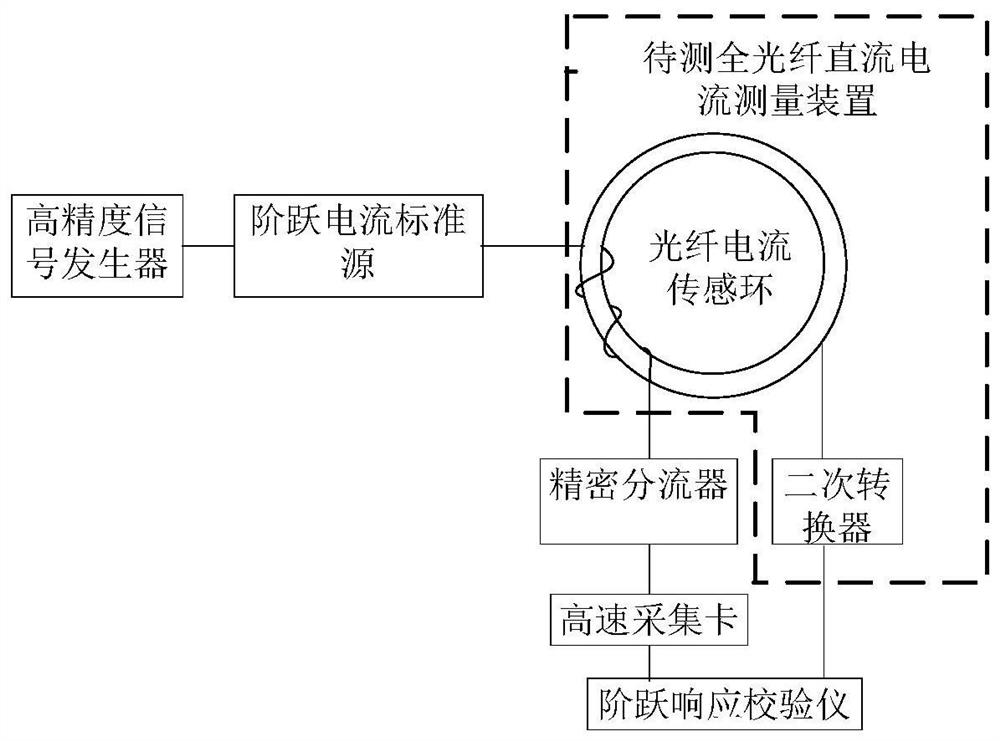
[0030] Such as figure 1 As shown, a step response test system of an all-fiber DC current measurement device for flexible DC transmission, including a current source for generating a step current signal, an all-fiber DC current measurement device to be tested, and a step response calibrator. The all-optical fiber direct current measuring device to be tested includes a fiber optic current sensing ring and a secondary converter, the current source and the fiber optic current sensing ring are connected to form a primary loop, and the fiber optic current sensing ring is also connected with a precision shunt and the secondary converter respectively. The secondary converter, the precisio...


PUM


Abstract

The invention discloses a step response testing system and method for an all-fiber direct current measuring device. The system includes a current source, an all-fiber direct current measuring device to be measured, a step response calibrator, and an all-fiber direct current measuring device to be measured. Including the fiber optic current sensing loop and the secondary converter, the current source and the fiber optic current sensing loop are connected to form a primary loop, and the fiber optic current sensing loop is also connected with a precision shunt and a secondary converter, and a precision shunt and a secondary converter. All the devices are connected with the step response calibrator, and the precision shunt is connected with the step response calibrator through a high-speed acquisition card. The invention also provides a step response testing method. The invention improves the test accuracy of the step response process of the all-fiber direct current measuring device, so that the test results can more accurately reflect the actual performance of the direct current measuring device, thereby effectively improving the ability to discriminate the performance of the direct current measuring device.

Description

technical field [0001] The invention relates to the technical field of flexible direct current transmission, in particular to a step response testing system and method of an all-fiber direct current measuring device. Background technique [0002] With the expansion of the grid construction scale year by year, especially the vigorous development of ultra-high voltage and ultra-high voltage direct current transmission projects, higher requirements are put forward for the direct current measurement device. The operation reliability and measurement accuracy of the direct current measurement device are directly related to the direct current transmission system. stable operation. Compared with the AC transmission system, the DC transmission system requires faster sampling speed and wider dynamic range for control and protection signals, which is particularly prominent in the flexible DC transmission system. When the DC side of the flexible DC transmission system fails, the loop i...

Claims


Application Information

Patent Timeline
Patent Type & Authority Patents(China)
IPC IPC(8): G01R35/00
CPCG01R35/00
Inventor 刘彬刘翔童悦邬雄叶国雄黄华熊俊军邓小聘代静汪英英
Owner CHINA ELECTRIC POWER RES INST
Learn More