
A detector for detecting tiny scratches on the surface of the car shaft

A detector and scratch technology, applied in the direction of optical testing flaws/defects, etc., can solve the problems of limited measurement accuracy of camera accuracy, inability to detect scratch depth features, insufficient scratch measurement accuracy, etc., to improve the repeatability of positioning accuracy. Effect

Inactive Publication Date: 2021-06-25
CHANGCHUN INST OF TECH
View PDF0 Cites 0 Cited by
  • Summary
  • Abstract
  • Description
  • Claims
  • Application Information

AI Technical Summary

Problems solved by technology

The lens detection method based on CCD imaging principle, which is applied in the industry to measure scratches, its measurement accuracy is limited by the accuracy of the camera, and the depth characteristics of scratches cannot be detected, and there are also shortcomings of insufficient scratch measurement accuracy

Method used


Image

  • A detector for detecting tiny scratches on the surface of the car shaft
  • A detector for detecting tiny scratches on the surface of the car shaft
  • A detector for detecting tiny scratches on the surface of the car shaft

Examples


specific Embodiment 1

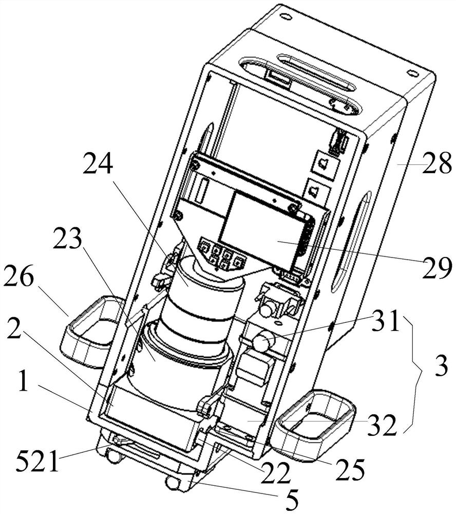
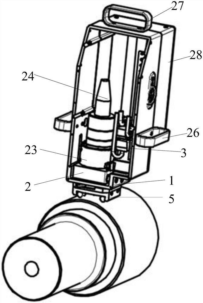
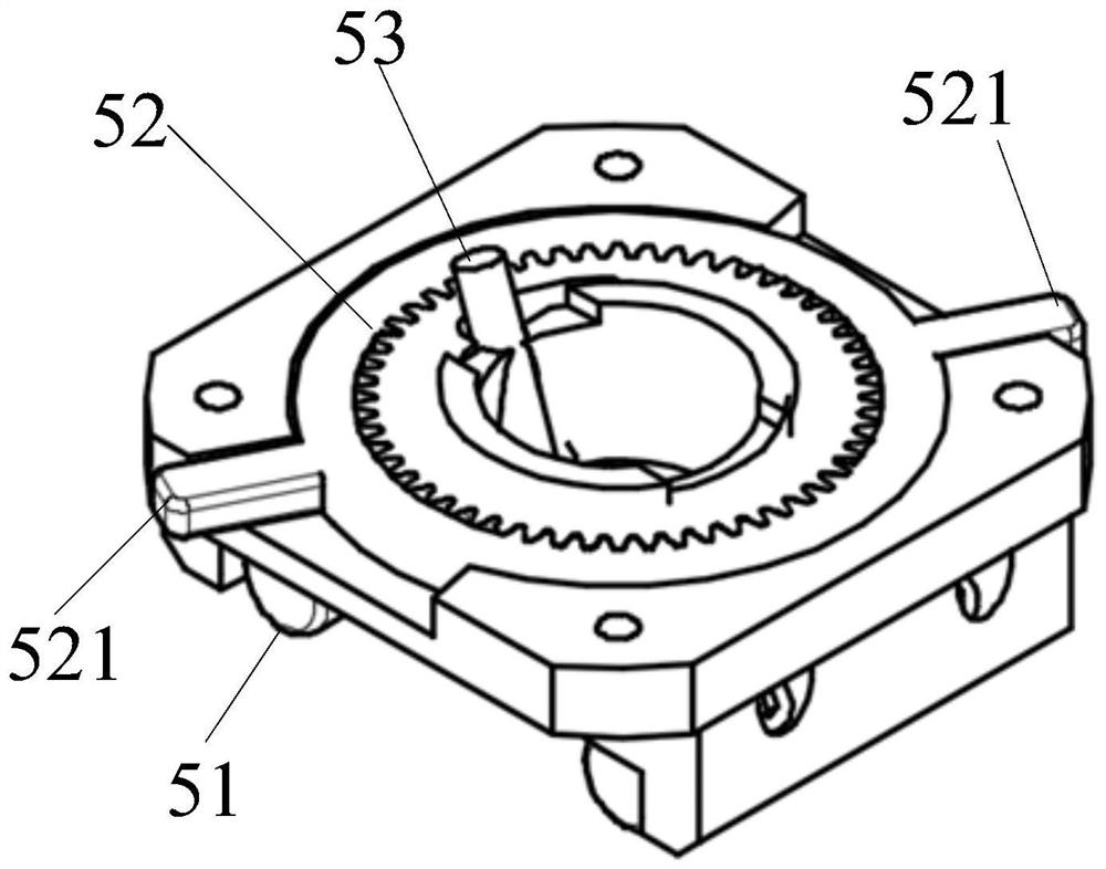
[0069] This embodiment is an embodiment of a micro-scratch detector on the surface. An oval groove is machined under the base as a detection window. The gear rotation mechanism is connected with the bottom of the base by bolts, and an endoscope lens is set on one side of it, which can roughly locate the scratch position, so that the detector can locate the scratch position. A sliding block moving device is installed inside the base, and an elliptical through hole is processed on the upper surface of the sliding block, and a through-hole plastic block is screwed on it. The probe is placed vertically in the plastic block, and the laser emitted by the probe can face the axis to be measured through the through hole. A pair of parallel through holes are processed in the side of the slide block, and linear bearings are arranged in them, and the cylindrical shaft passes through the linear bearings and is fixed on both sides of the base. An eccentric wheel transmission mechanism is ...

specific Embodiment 2

[0071] When the endoscope lens is positioned at the scratch in the horizontal position, after turning the gear to rotate the wrench, the detector can detect the scratch depth in the horizontal position.

[0072] The above-mentioned sensor probe can be a spectral confocal sensor or a laser sensor.

[0073] Considering the cost performance and accuracy requirements of the detection device, a spectral confocal lens sensor can be selected to measure the depth and width of scratches. The detection is quickly completed online in a non-contact manner, which improves the speed of scratch depth measurement, ensures the validity of the detection data, and solves the efficiency and accuracy problems caused by the current manual detection.


PUM


Abstract

The invention discloses a detector for detecting tiny scratches on the surface of an axle, comprising: a base arranged inside a casing, a slider moving device, an eccentric wheel transmission mechanism, a grating ruler reading head moving device and a gear rotation mechanism. Among them: use the endoscope lens to roughly locate the scratch position and then align the sensor probe to the side of the scratch to complete the rough positioning of the scratch. After the rough positioning is completed, the eccentric wheel mechanism is used to drive the slider moving device to cross the scratch position, and the height difference in this process is obtained to complete the extraction of the depth information of the scratch. The acquisition of width information depends on the two points of sharp drop in displacement at the beginning and end of the process, and the distance between these two points is obtained as width information. The eccentric wheel transmission mechanism and the moving device of the grating ruler reading head can ensure accurate control of the measurement position of the sensor probe and improve the repeat positioning accuracy.

Description

technical field [0001] The invention relates to the technical field of machine vision, and relates to a detector for detecting tiny scratches on the surface of an axle. Background technique [0002] Machine vision is a comprehensive technology that integrates digital image processing, machinery, control, optics, computer and other technologies. Machine vision systems can realize non-contact detection of targets, can quickly acquire a large amount of information, and are easy to process automatically. Therefore, machine vision technology has attracted people's attention as an important detection technology, and has been more and more widely used in the detection field. [0003] At present, the measurement of surface scratches on shaft parts still relies on manual traditional detection. According to on-site feedback, the traditional detection method is that inspectors only rely on fingers to touch the scratch position for depth and width detection. Inspectors are easily affe...

Claims


Application Information

Patent Timeline
Patent Type & Authority Patents(China)
IPC IPC(8): G01N21/95
CPCG01N21/95
Inventor 高金刚王华王立东孙志鹏张克木赵伟甫张爽王文忠潘鸣宇侯岱双杨青山
Owner CHANGCHUN INST OF TECH
Learn More