
Variable liquid distributor and mounting method thereof

An installation method and liquid separator technology are applied in refrigeration and liquefaction, fluid circulation arrangements, mechanical equipment, etc., which can solve problems such as uneven heat dissipation of evaporators, affecting heat exchange capacity, and decline in heat exchange efficiency, and achieve the best air-conditioning performance Good, easy to process and assemble, and reduce flow resistance

Pending Publication Date: 2019-07-23
泰铂(上海)环保科技股份有限公司
View PDF8 Cites 1 Cited by
  • Summary
  • Abstract
  • Description
  • Claims
  • Application Information

AI Technical Summary

Problems solved by technology

[0003] When an odd number of flow paths is used to divide the flow, the use of the existing liquid separator will cause uneven and unstable liquid separation due to the resistance caused by the different number of U-shaped tubes in the heat exchanger, especially under the condition of alternating current. More serious, heat transfer efficiency drops, causing problems such as water blowing
The existence of the above deficiencies will cause the evaporator to dissipate heat unevenly, thereby affecting its heat exchange capacity

Method used


Image

  • Variable liquid distributor and mounting method thereof
  • Variable liquid distributor and mounting method thereof
  • Variable liquid distributor and mounting method thereof

Examples


Embodiment

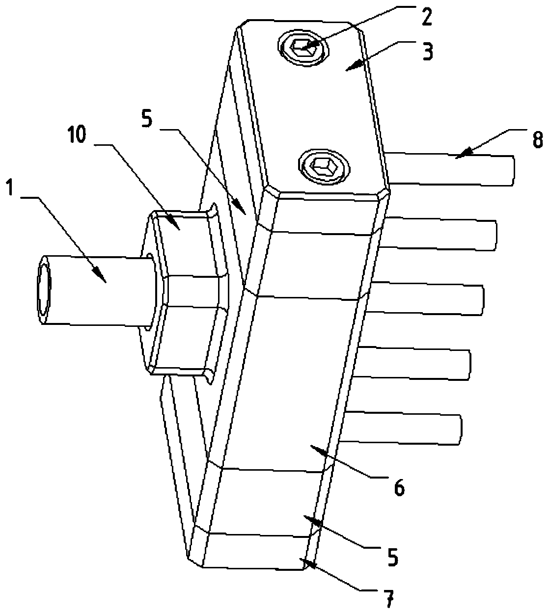
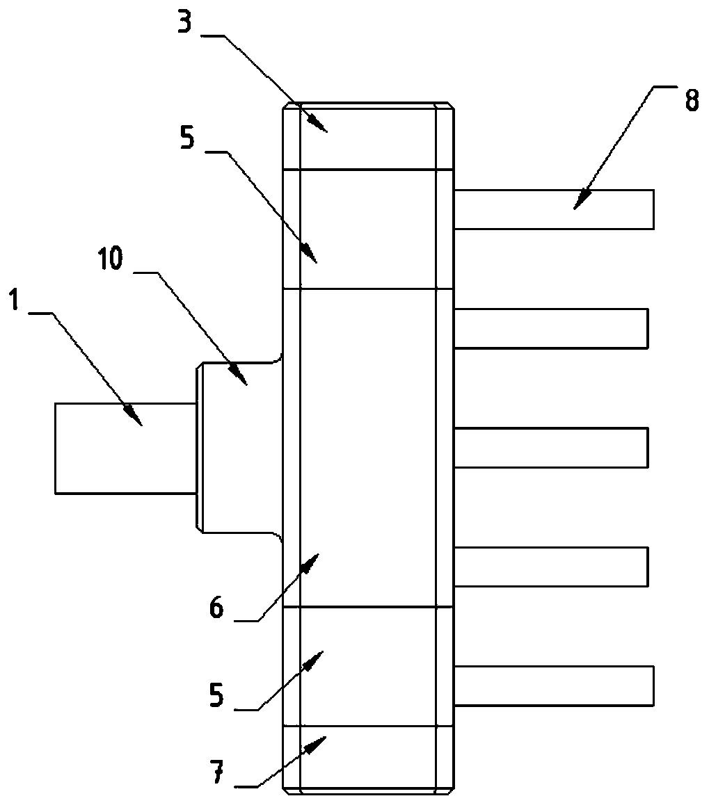
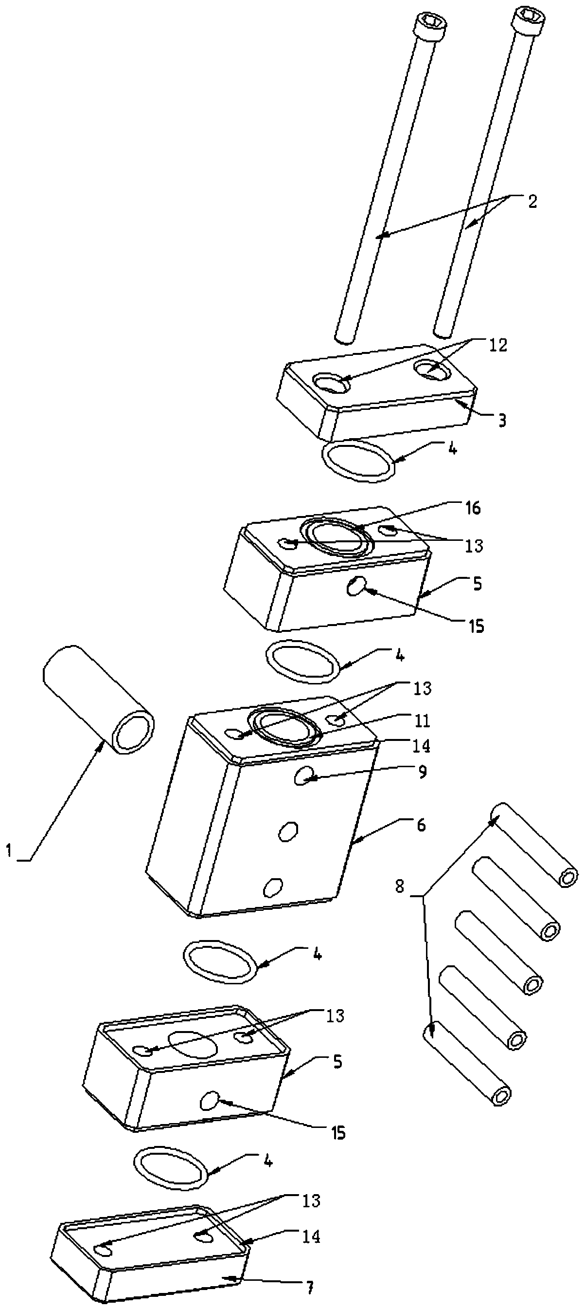
[0034] This embodiment provides a variable liquid separator, whose structure is detailed in the attached figure 1 , 2 As shown in and 3: it includes the upper seal cover 3, the main body 6 and the lower seal cover 7 which are penetrated and fixed by the hexagon socket bolt 2 from top to bottom, and also includes the O-ring 4, the second connecting pipe 1 and the first connecting pipe 8 The main body 6 is a cavity structure, and its side wall is provided with a plurality of first connecting pipe mounting holes 9 communicating with the cavity, and its other side wall is provided with a second connecting pipe mounting hole communicating with the cavity 10, its top end surface and bottom end surface are provided with the first O-shaped groove 11 that clamps the O-ring 4; the first connecting pipe 8 is provided with multiple ones, one end of which is inserted into the first connecting pipe installation hole 9, and the other One end is connected to the core body; one end of the sec...


PUM


Abstract

The invention provides a variable liquid distributor. The variable liquid distributor comprises an upper sealing cover, a main body and a lower sealing cover which are fixed from top to bottom in sequence by penetrating through inside hexagonal bolts; the variable liquid distributor also comprises O-shaped rings, second connecting pipes and first connecting pipes; the main body is of a cavity structure; each of the top end surface and the bottom end surface of the main body are provided with a first O-shaped groove which is used for clamping the O-shaped ring; a plurality of the first connecting pipes are arranged; one end of each first connecting pipe is inserted into a first connecting pipe mounting hole of the main body; the other end of each first connecting pipe is connected with a core body; one end of each second connecting pipe is inserted into a second connecting pipe mounting hole of the main body; and the other end of each first connecting pipe is connected with a pressing plate of an expansion valve. The invention also provides a mounting method for the variable liquid distributor. Different liquid distributing requirements are met by regulating the number of standard pieces; the area of gasified refrigerant liquid flow can be increased; the flow resistance is reduced; a refrigerant does not produce an airflow sound; and moreover, the heat exchange time of the refrigerant in the core body can be regulated according to a design requirement.

Description

technical field [0001] The invention relates to the field of liquid distributors, in particular to a variable liquid distributor and an installation method thereof. Background technique [0002] The liquid separator is an important part in the vapor compression refrigeration cycle system, which is installed between the throttling device and the evaporator, and is used to evenly distribute the refrigerant flowing out of the throttling device to each branch flow path of the evaporator middle. The main pipe of the liquid separator is usually connected to a main liquid inlet pipe, and a plurality of liquid separation holes are evenly distributed on the liquid separation head. The outlet of the liquid separation hole is connected to a branch pipe. The diameter of each branch pipe is the same, and the other end of the branch pipe is connected to the evaporator. Its function is to generate uniform flow distribution as much as possible, so that the heat exchange of each section of ...

Claims


Application Information

Patent Timeline
Patent Type & Authority Applications(China)
IPC IPC(8): F25B41/00F25B41/40
CPCF25B2500/09F25B41/40
Inventor 陶林谢虹朴雨植金奉奎毛文杰
Owner 泰铂(上海)环保科技股份有限公司
Learn More