Moving body

A technology of moving body and oxidant gas, applied in the field of moving body, can solve the problems such as the damage of the installation state of the internal cooler, and achieve the effect of stable maintenance

Active Publication Date: 2019-07-23
TOYOTA JIDOSHA KK
View PDF6 Cites 0 Cited by
  • Summary
  • Abstract
  • Description
  • Claims
  • Application Information

AI Technical Summary

Problems solved by technology

However, depending on the mounting method of the bracket, there is a possibility that the installation state of the intercooler may be damaged due to the vibration of the mobile body during driving and the interaction of the self-weight of the intercooler.

Method used


Image

  • Moving body
  • Moving body
  • Moving body

Examples


Embodiment Construction

[0024] Hereinafter, one embodiment of the moving body according to the present invention will be described in detail based on the drawings.

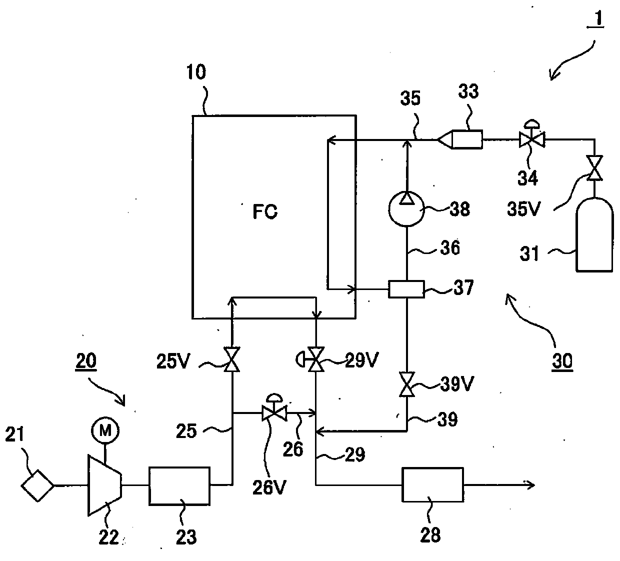
[0025] First, refer to figure 1 The moving body according to the present invention will be described. in figure 1 Here, the mobile body 1 is a vehicle such as a passenger car, and a fuel cell stack 10 is mounted on the front part of the front, and a compressor 22 and an internal cooler 23 are mounted as auxiliary equipment. The compressor 22 and the internal cooler 23 constitute an oxidant gas supply system 20 that supplies oxidant gas to the fuel cell stack 10.

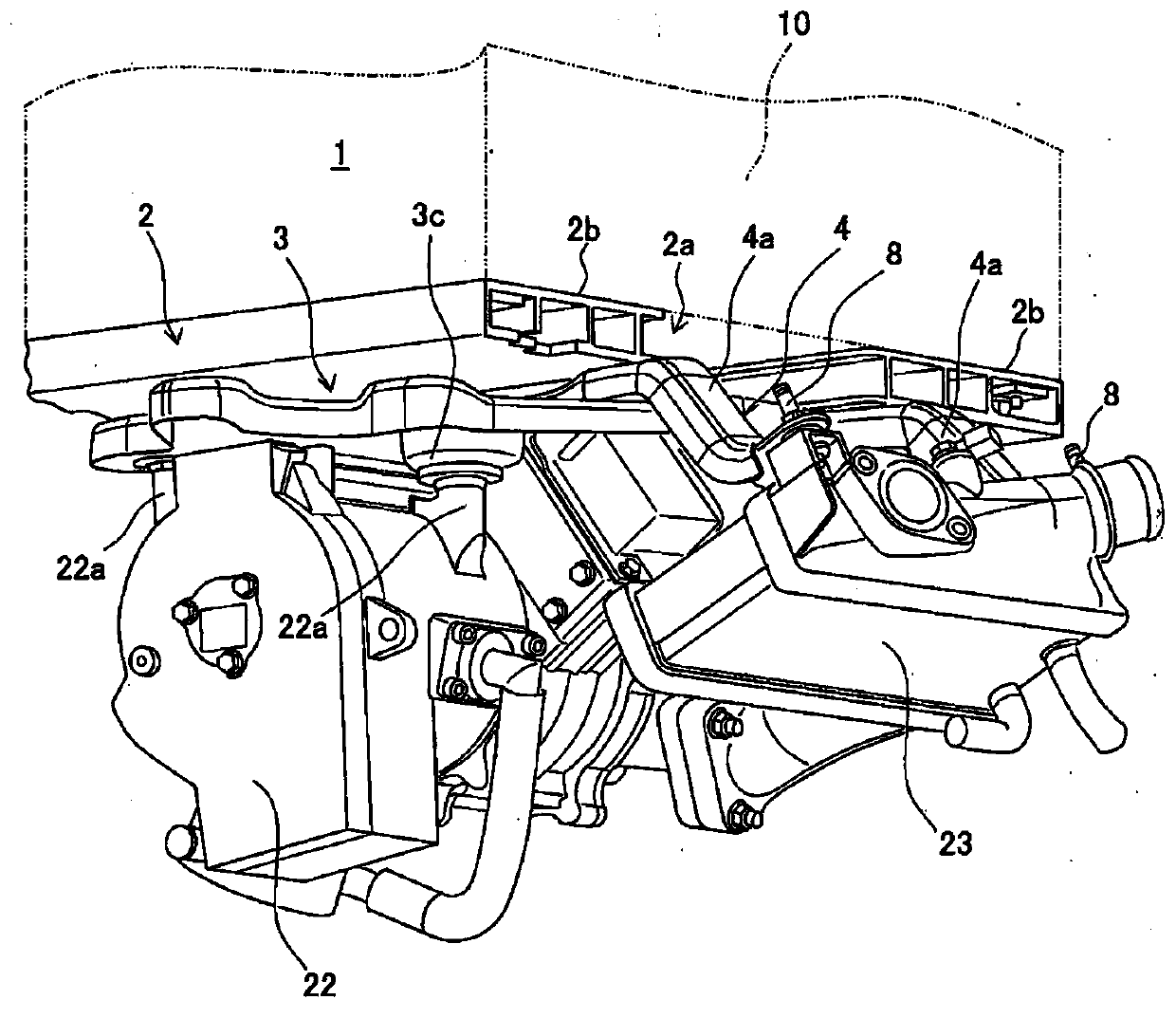
[0026] The fuel cell stack 10 is mounted on the upper part of the stack frame 2, the compressor 22 is mounted and fixed to the lower part of the stack frame 2 in a suspended state via the compressor bracket 3, and the intercooler 23 is via the intercooler bracket 4 It is fixed to the lower part of the battery pack frame 2 in a suspended state. In addition, a fuel gas supply source...


PUM


Abstract

The invention provides a moving body. The moving body (1) configured to reduce damage on the mounting state of an intercooler even when traveling is provided. The moving body (1) includes an intercooler bracket (4) that has a pair of arms (4a,4a) extending from a stack frame (2). At distal end sides of the respective arms (4a), an intercooler (23) is mounted to the respective arms (4a). At base end sides of the respective arms (4a), the intercooler bracket (4) is secured to the stack frame (2). A connecting portion (4b) that connects the pair of arms (4a,4a) is integrally formed with the pairof arms (4a,4a).

Description

Technical field [0001] The present invention relates to a mobile body such as a vehicle, and particularly to a mobile body equipped with a fuel cell. Background technique [0002] Conventionally, as such a moving body, there is a fuel cell vehicle described in Patent Document 1. This fuel cell vehicle includes a fuel cell assembly, which has an assembly frame, and a fuel cell assembly including a fuel cell and auxiliary machinery integrally mounted on the assembly frame, and an air compressor as an auxiliary machinery. [0003] Patent Document 1: Japanese Patent Application Publication No. 2017-74819 [0004] Among them, the fuel cell vehicle with the above structure does not have an intercooler that cools high-temperature air compressed by an air compressor. If the intercooler is installed on the frame, it will interact with other auxiliary equipment. Together, they are mounted on the lower part of the frame via a bracket. However, depending on the mounting method of the bracket,...

Claims


Application Information

Patent Timeline
Patent Type & Authority Applications(China)
IPC IPC(8): B60L50/71B60K1/04
CPCB60L50/71B60K1/04H01M2250/20H01M8/04089H01M8/04201H01M8/04067H01M8/04014B60L3/0053B60L50/70B60L58/33Y02T10/70Y02T90/14Y02T10/7072B60L50/72H01M8/04074H01M8/04111H01M8/04708H01M8/2475
Inventor 松本博义武山诚
Owner TOYOTA JIDOSHA KK
Why Eureka
Try Eureka