
Connector for card

A technology of card connectors and recesses, which is applied in the direction of connection, parts of connecting devices, electrical components, etc., can solve the problems of fierce competition for card connectors

Inactive Publication Date: 2010-07-28
JST MFG CO LTD
View PDF4 Cites 0 Cited by
  • Summary
  • Abstract
  • Description
  • Claims
  • Application Information

AI Technical Summary

Problems solved by technology

[0017] However, mass-produced card connectors compete fiercely in terms of cost, and card connectors with simpler locking mechanisms are being sought.

Method used


Image

  • Connector for card
  • Connector for card
  • Connector for card

Examples


Embodiment Construction

[0076] Hereinafter, the best mode for carrying out the present invention will be described with reference to the drawings.

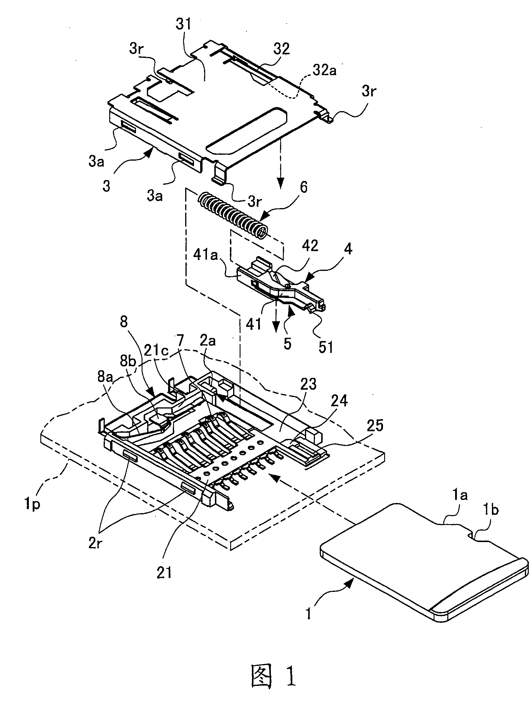
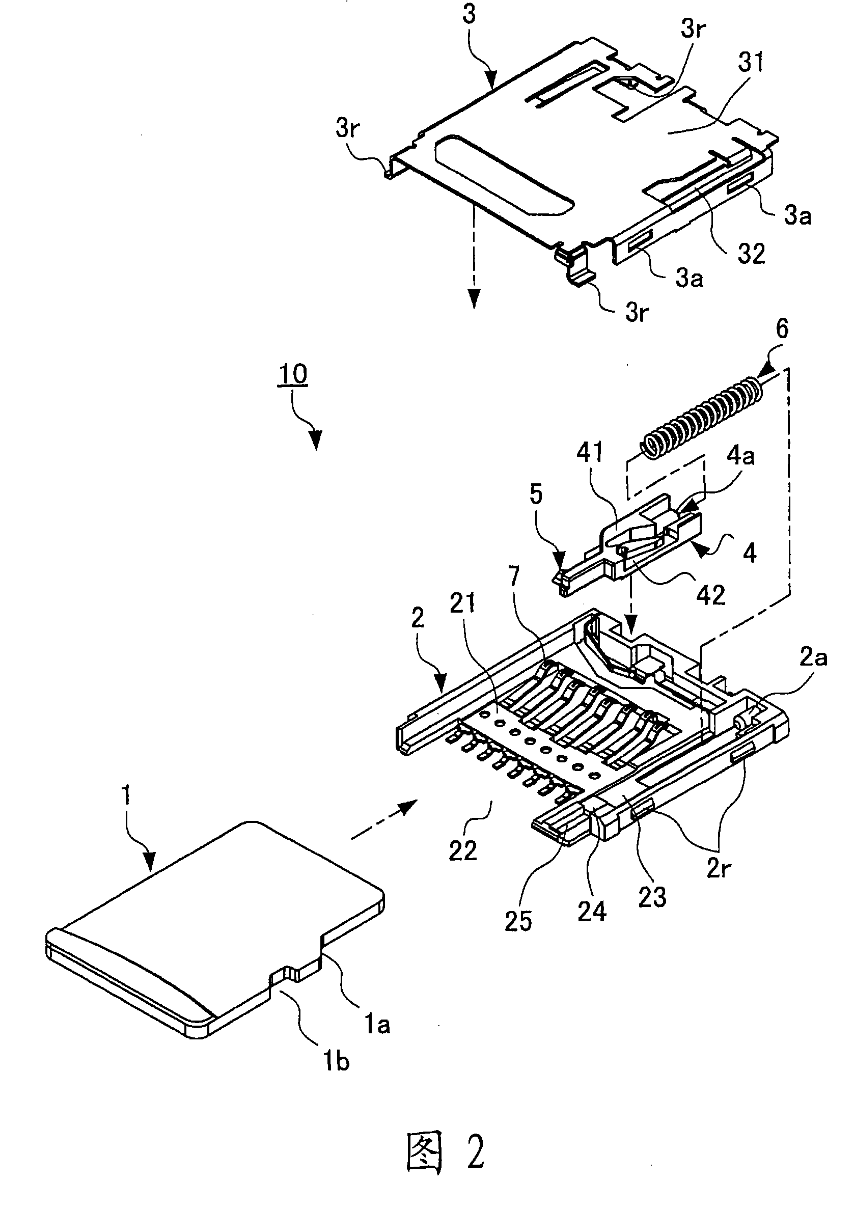
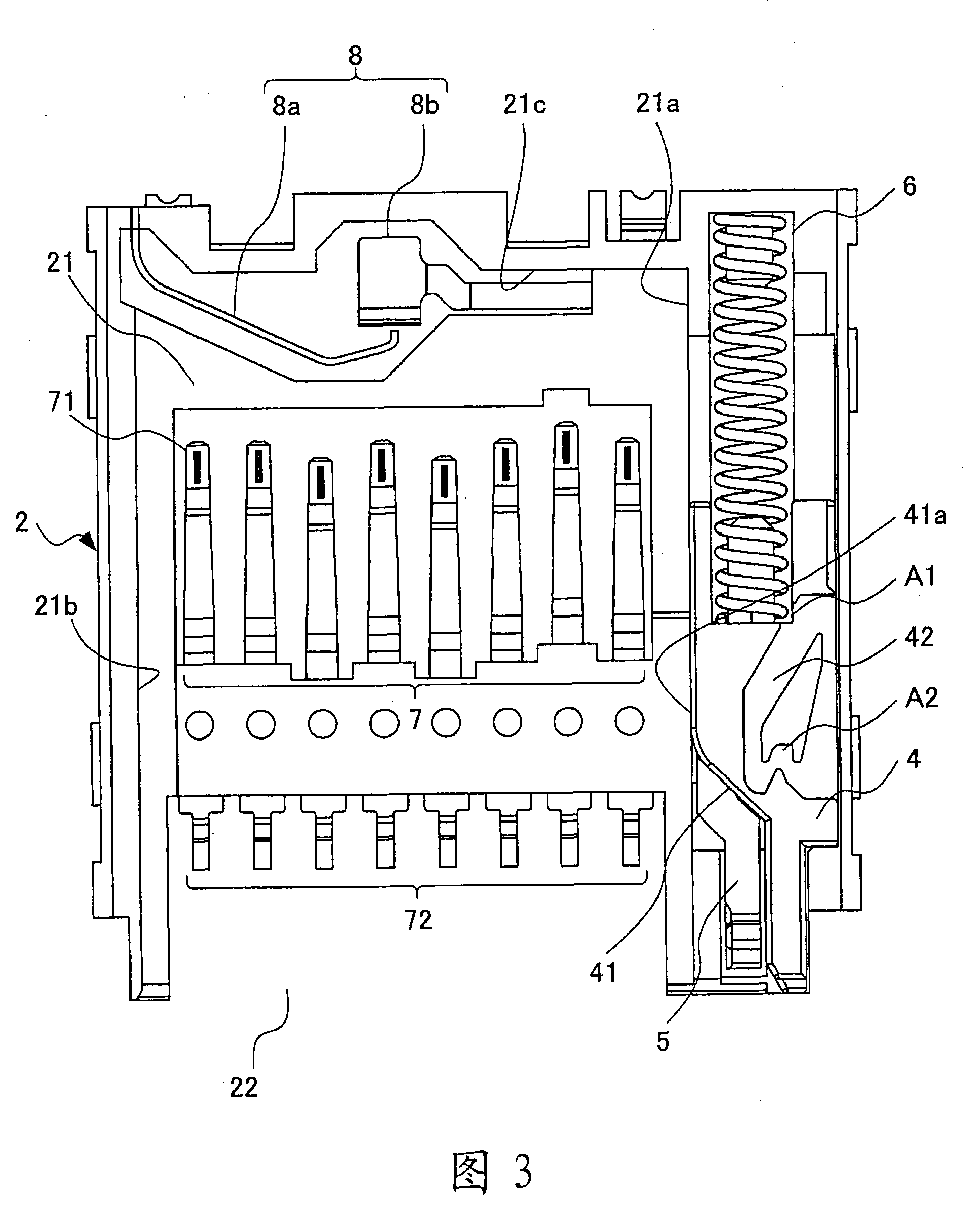
[0077] figure 1 It is an exploded perspective view showing an embodiment of the card connector (hereinafter simply referred to as a connector) of the present invention. figure 2 is a three-dimensional exploded assembly view of the connector of the above embodiment, from the figure 1 View the connector from different directions. image 3 It is a plan view of the connector of the said embodiment, and is a state view with a cover removed.

[0078] 4 is a perspective external view of a slider included in the connector of the above embodiment, viewing the slider from the back. Figure 5 It is a perspective external view of the cover included in the connector of the above-mentioned embodiment, and the cover is viewed from the back. Fig. 6 is a perspective view of the connector of the above embodiment, showing a state in which a card is attached. Figure ...


PUM


Abstract

The present invention provides a connector for card, the connector for card has a locking mechanism having simple structure. The connector includes: a casing, having a recess part of inserting or pulling the card; and a cover, covering the casing. A sliding part has a card clamp piece which is pressing against the bevel edge of the card, parallelly advancing and retreating with the card. A compression coiled spring forces to the sliding part. A plate spring is integrity with the cover. The front end of the plate spring is driven move by a heart shaped cam groove, capable of locking the sliding part.

Description

technical field [0001] The present invention relates to a card connector. In particular, the present invention relates to a structure of a card connector electrically connected to a memory card such as an SD (Secure Digital) card when the memory card is inserted. Background technique [0002] A card-type storage device, that is, a memory card, uses a flash memory as a storage medium. Since the memory card is very small and consumes little power for reading and writing data, it is widely used as a recording medium for portable information devices such as mobile phones with cameras and PDAs (Personal Digital Assistance: Personal Digital Assistant). [0003] Compared with disk storage devices such as a floppy disk (FD) or a magneto-optical disk (MO), the memory card has a small storage capacity and is expensive. However, due to the effect of mass production accompanied by technological progress in recent years and the spread of devices using memory cards, memory cards have a ...

Claims


Application Information

Patent Timeline
Patent Type & Authority Patents(China)
IPC IPC(8): H01R13/629H01R12/16
Inventor 浅冈章宏
Owner JST MFG CO LTD
Learn More