Rotary centre

A tip and thimble technology, which is applied in the direction of tailstock/top, turning equipment, tool holder accessories, etc., can solve the problems of low production efficiency and achieve the effect of increasing connection stability

Inactive Publication Date: 2019-07-23
CHONGQING HONGGANG CNC MACHINE TOOL
View PDF7 Cites 2 Cited by
  • Summary
  • Abstract
  • Description
  • Claims
  • Application Information

AI Technical Summary

Problems solved by technology

[0003] However, the existing adjustment of the coaxiality of the top is usually achieved by adjusting the distance between the bottom plate and the tailstock to realize the adjustment of the coaxiality of the thimble, and such an adjustment method requires more than ten minutes even for experienced workers. It is quite time-consuming, resulting in low production efficiency, so our company has developed and improved how to quickly adjust the coaxiality of the thimble and the mandrel

Method used


Image

  • Rotary centre
  • Rotary centre
  • Rotary centre

Examples


Embodiment 1

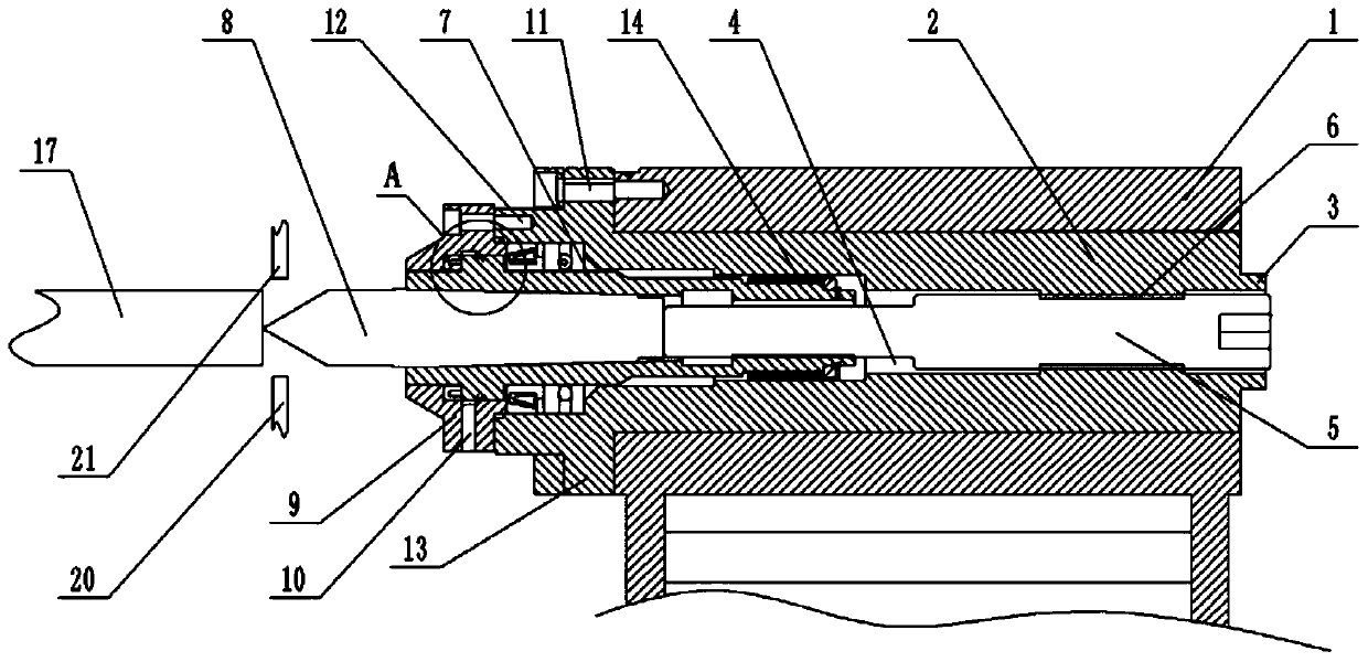
[0036] Such as figure 1 As shown, a rotating top includes a sleeve 2, and the sleeve 2 sequentially includes a mounting hole, a bearing hole and an eccentric hole 4 from left to right, and the mounting hole and the bearing hole are coaxially arranged and are coaxially arranged with the sleeve 2 The eccentric hole 4 is arranged eccentrically relative to the sleeve 2 . The left part of the sleeve 2 is fixed with an annular connection plate 13, and in order to ensure assembly stability, the connection plate 13 and the sleeve 2 are integrally formed. There are several arc-shaped holes uniformly distributed along the circumferential direction on the connection plate 13. When the sleeve 2 is installed on the tailstock 1 of the machine tool, the sleeve 2 is inserted into the tailstock 1, and the right end surface of the connection plate 13 is offset against the tailstock 1. The second bolt 11 is passed through the arc-shaped hole and screwed into the tailstock 1 to realize the fixin...

Embodiment 2

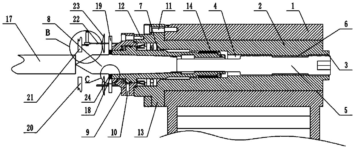
[0046] Compared with embodiment 1, present embodiment, as image 3 As shown, the dust-proof structure also includes a driving gear 18 fixed on the mandrel 7 away from the left end of the ejector rod 5. The inner diameter of the central hole of the driving gear 18 is greater than the outer diameter of the thimble 8, and the sealing cover 9 is rotatably connected with a rotating rod 22. The driven gear 19 meshed with the driving gear 18 is fixed on the rod 22, and several blades 23 are evenly distributed along the circumferential direction on the rotating rod 22. Figure 5 As shown, the inner wall of the central hole of the driving gear 18 is fixed with an annular sealing washer 24 , the inner wall of the sealing washer 24 is opposed to the thimble 8 , and a plurality of rotating rods 22 are provided and evenly distributed along the circumferential direction of the sealing cover 9 .

[0047] combine Figure 4 As shown, the left end of the rotary rod 22 on the top of the seal co...


PUM


Abstract

The invention belongs to the field of numerical control machine tool components, and particularly discloses a rotary centre which comprises a sleeve. A connecting disc used for being connected with amachine tool tailstock is fixed on the outer wall of the sleeve; a mandrel is coaxially and rotationally connected in the sleeve; an ejector pin is arranged the mandrel in a taper matched mode; the tip end of the ejector pin extends out of the mandrel; one end, in the mandrel, of the ejector pin is a small-diameter end; the inner part of the sleeve is eccentrically and fixedly connected with an ejector rod; the ejector rod is inserted into the mandrel and abuts against the end part of the ejector pin; and a dustproof structure is arranged on the part, extending out of the mandrel, of the ejector pin; the dustproof structure comprises a negative pressure fan; and the suction end of the negative pressure fan faces the tip end of the ejector pin. By adopting the scheme, the requirement of rapidly adjusting the taper of the ejector pin can be met.

Description

technical field [0001] The invention belongs to the field of CNC machine tool components, and in particular relates to a rotary top. Background technique [0002] The top plays the role of positioning support for the workpiece during the machining process. The commonly used top is usually composed of a thimble, a clamping device, a housing, a fixed pin and a mandrel, and the tail of the thimble is matched with the taper of the mandrel, and the top is assembled during assembly. On the tailstock of the machine bed, and the tailstock can slide on the machine bed. In the machining process, it is usually necessary to adjust the coaxiality of the tip. The main reason for this situation is that the thimble is matched with the taper of the mandrel, and impurities such as external coolant and metal dust will enter into the machining process. The slope of the taper fit causes greater wear between the thimble and the mandrel. Therefore, after the tip has been in service for a long tim...

Claims


Application Information

Patent Timeline
Patent Type & Authority Applications(China)
IPC IPC(8): B23B23/04
CPCB23B23/04
Inventor 汪传宏
Owner CHONGQING HONGGANG CNC MACHINE TOOL
Why Eureka
Try Eureka