
Cantilever beam piezoelectric microspray mechanism capable of spraying high-viscosity fluid

A cantilever beam type, fluid technology, applied in the direction of injection device, liquid injection device, etc., can solve the problems of complex structure, injection failure of micro-injection mechanism, etc., and achieve the effect of small voltage amplitude

Active Publication Date: 2019-07-23
HARBIN INST OF TECH
View PDF8 Cites 3 Cited by
  • Summary
  • Abstract
  • Description
  • Claims
  • Application Information

AI Technical Summary

Problems solved by technology

The vibrator of the traditional piezoelectric micro-spray mechanism is fully constrained and the deformation is small; due to the influence of viscous resistance, it is difficult to realize the high-viscosity fluid through low pressure. The high pressure will cause the elastic film to protrude to the outside of the cavity, which will cause the injection failure of the micro-spray mechanism; at the same time, the existing piezoelectric micro-spray mechanism still has the problem of requiring a stabilized oil storage tank and complex structure

Method used


Image

  • Cantilever beam piezoelectric microspray mechanism capable of spraying high-viscosity fluid
  • Cantilever beam piezoelectric microspray mechanism capable of spraying high-viscosity fluid
  • Cantilever beam piezoelectric microspray mechanism capable of spraying high-viscosity fluid

Examples


Embodiment Construction

[0026] It should be noted that, in the case of no conflict, the embodiments of the present invention and the features in the embodiments can be combined with each other.

[0027] In addition, the high-viscosity fluid mentioned in the embodiments of the present invention refers to a fluid with a viscosity greater than 50 cP.

[0028] The present invention will be described in detail below with reference to the accompanying drawings and examples.

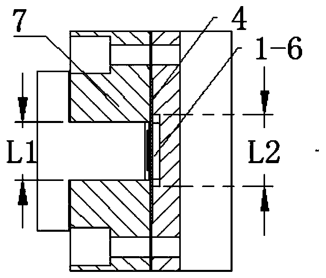
[0029] Such as Figure 1-Figure 7 As shown, a cantilever beam piezoelectric micro-injection mechanism capable of spraying high-viscosity fluids includes a base 1, a porous liquid storage structure 3, a flexible film 4, a copper sheet 5, piezoelectric ceramics 6, an upper cover plate 7, and a copper sheet The pressure plate 8 and the nozzle 9 are provided with a liquid reservoir 1-3 on the left side of the upper surface of the base 1, an installation groove 1-7 is provided on the right side of the upper surface of the base 1, and a fl...


PUM


Abstract

The invention provides a cantilever beam piezoelectric microspray mechanism capable of spraying high-viscosity fluid. The mechanism comprises a base, a porous liquid storage structure, a flexible thinfilm, a copper sheet, piezoelectric ceramic, an upper cover plate, a copper sheet pressing plate and spray nozzles. A liquid storage tank is formed in the left side of the upper surface of the base,a mounting groove is formed in the right side of the upper surface of the base, a fluid circulating groove is formed in the bottom of the mounting groove, the liquid storage tank communicates with thefluid circulating groove through a liquid storage tank outlet and a fluid flow channel inlet in sequence, the porous liquid storage structure is arranged in the liquid storage tank, the flexible thinfilm is arranged in the positioning groove and completely covers the fluid circulating groove, the upper cover plate constrains the normal outward freedom degree of the flexible thin film, the coppersheet is attached to the flexible thin film, the piezoelectric ceramic is attached to the copper sheet, the copper sheet pressing plate penetrates through the upper cover plate and is tightly pressedto the left end of the copper sheet to form a cantilever beam structure, the spray nozzles are formed in the lower surface of the base and communicate with a fluid channel, and a closed cavity accommodating the high-viscosity fluid is defined between the flexible thin film and the base. By means of the cantilever beam piezoelectric microspray mechanism, the high-pressure high-viscosity fluid canbe sprayed.

Description

technical field [0001] The invention belongs to the field of micro-droplet spraying, and in particular relates to a cantilever beam piezoelectric micro-spraying mechanism capable of spraying high-viscosity fluid. Background technique [0002] The micro-droplet ejection mechanism based on piezoelectric actuation is widely used in the fields of material chemical industry, biomedicine, micro-electromechanical system manufacturing, etc., mainly to realize the functions of ejection and control of micro-droplets. The vibrator of the traditional piezoelectric micro-spray mechanism is fully constrained and the deformation is small; due to the influence of viscous resistance, it is difficult to realize the high-viscosity fluid through low pressure. The high pressure will cause the elastic film to protrude to the outside of the cavity, which will cause the injection failure of the micro-injection mechanism; at the same time, the existing piezoelectric micro-injection mechanism still h...

Claims


Application Information

Patent Timeline
IPC IPC(8): B05B17/06B05B15/40
CPCB05B15/40B05B17/0615B05B17/0676
Inventor 李锴陈维山刘军考刘英想李恒禹王润举
Owner HARBIN INST OF TECH
Learn More