
Shunt and manufacturing method thereof

A manufacturing method and shunt technology, which are applied in the manufacturing of contact parts, riveting connection, etc., can solve the problems of virtual welding in the welding area, prone to air explosion, air bubbles, etc., and achieve the effect of fast connection and avoiding virtual welding.

Active Publication Date: 2019-07-19
陈敏
View PDF4 Cites 0 Cited by
  • Summary
  • Abstract
  • Description
  • Claims
  • Application Information

AI Technical Summary

Problems solved by technology

The silver welding process has relatively high technical requirements for operators, and welding defects such as virtual welding, false welding, missing welding, and air bubbles often appear in the welding area, and air explosion is prone to occur at the welding interface under the condition of overcurrent
Therefore, the use of welding technology to connect the terminal and the resistance rod not only affects the structural stability of the shunt, but also affects the service life of the shunt, and also increases the scrap rate of the shunt manufacturing.

Method used


Image

  • Shunt and manufacturing method thereof
  • Shunt and manufacturing method thereof
  • Shunt and manufacturing method thereof

Examples


Embodiment Construction

[0029] In order to make the purpose, technical solutions and advantages of the embodiments of the present invention more clear, the technical solutions of the embodiments of the present invention will be clearly and completely described below in conjunction with the drawings of the embodiments of the present invention. Apparently, the described embodiments are some, not all, embodiments of the present invention. Based on the described embodiments of the present invention, all other embodiments obtained by persons of ordinary skill in the art without creative efforts shall fall within the protection scope of the present invention.

[0030] Unless otherwise defined, the technical terms or scientific terms used in the present invention shall have the usual meanings understood by those skilled in the art to which the present invention belongs. "First", "second" and similar words used in the present invention do not indicate any order, quantity or importance, but are only used to d...


PUM


Abstract

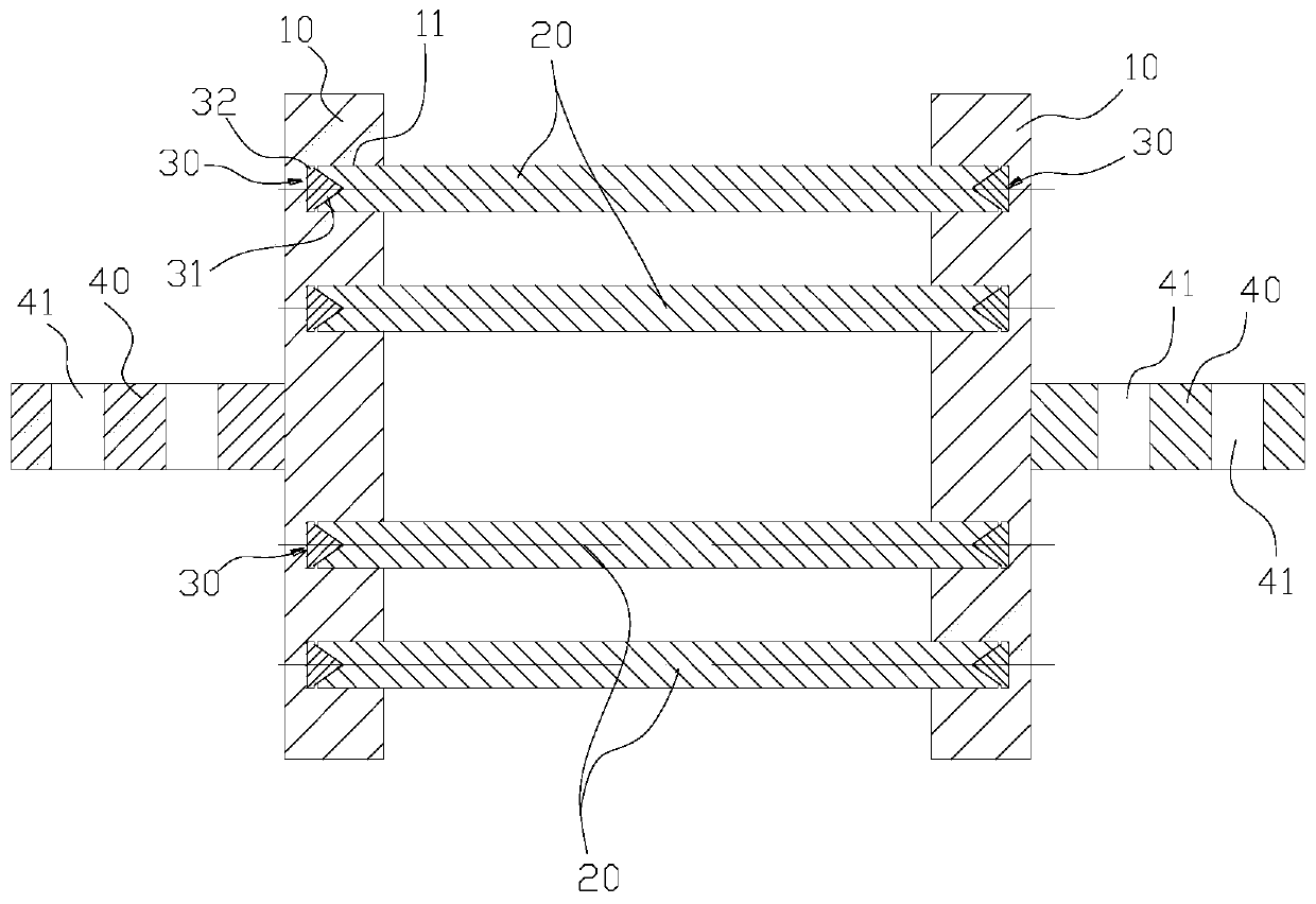
The invention discloses a shunt and a manufacturing method thereof. The shunt comprises plate-shaped wiring terminals, resistance rods and rivets, wherein the two plate-shaped wiring terminals are oppositely arranged; the two plate-shaped wiring terminals are provided with insertion holes in matrix arrangement, and the insertion holes are blind holes formed in the inner side plate surfaces of theplate-shaped wiring terminals; the multiple resistance rods are in one-to-one correspondence with the insertion holes, wherein the two ends of each resistance rod are provided with mortise holes respectively, and the mortise holes are conical; each rivet comprises a head part and a cap part, wherein the head part of the rivet extends into the corresponding mortise hole; and the two ends of each resistance rod are pressed into corresponding insertion holes of the two plate-shaped wiring terminals respectively, so that the tail part of the rivet is extruded by the hole bottom of the corresponding insertion hole.

Description

technical field [0001] The invention relates to the technical field of electric equipment, in particular to a shunt and a manufacturing method thereof. Background technique [0002] In the prior art, the plate-shaped terminal of the shunt and the resistance bar are usually connected and fixed by a silver soldering process. The silver welding process has relatively high technical requirements for operators, and welding defects such as virtual welding, false welding, missing welding, and air bubbles often occur in the welding area, and air bursts are prone to occur at the welding interface under overcurrent conditions. Therefore, the use of welding technology to connect the terminal and the resistance rod not only affects the structural stability of the shunt, but also affects the service life of the shunt, and also increases the scrap rate of shunt manufacturing. Contents of the invention [0003] In view of the above-mentioned technical problems existing in the prior art,...

Claims


Application Information

Patent Timeline
Patent Type & Authority Applications(China)
IPC IPC(8): H01R4/06H01R43/16
CPCH01R4/06H01R43/16
Inventor 陈敏
Owner 陈敏
Learn More