
Stress Calculation Method of Steel-Concrete Composite Beam

A calculation method and technology of composite beams, applied in computer-aided design, design optimization/simulation, instruments, etc., can solve problems such as stress changes of main beams of composite beam cable-stayed bridges, inability to effectively analyze sudden changes in shear lag displacement boundary conditions, etc.

Inactive Publication Date: 2020-11-10
CHENGDU UNIVERSITY OF TECHNOLOGY
View PDF5 Cites 0 Cited by
  • Summary
  • Abstract
  • Description
  • Claims
  • Application Information

AI Technical Summary

Problems solved by technology

[0005] The purpose of the present invention is to provide a kind of stress calculation method of steel-concrete composite beam, to alleviate existing in the prior art in the composite beam cable-stayed bridge construction process, utilize existing stress calculation method to be unable to effectively analyze construction process due to The sudden change of the shear lag displacement boundary condition caused by the concentrated bending moment and axial force, and the technical problems of the stress change of the main girder of the composite girder cable-stayed bridge caused by factors such as the constant change of the load and the shear lag displacement boundary condition during the construction process

Method used

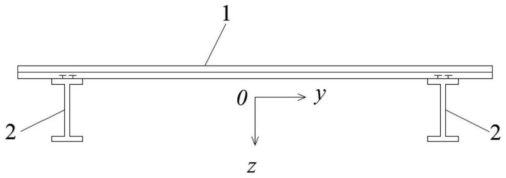
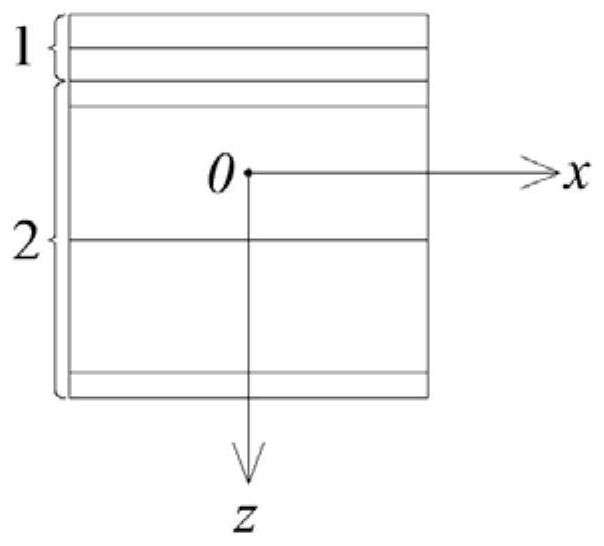
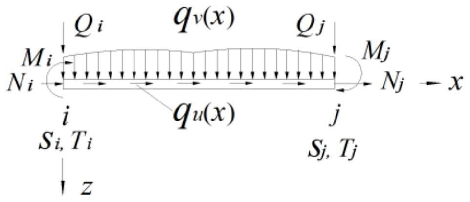

Image

  • Stress Calculation Method of Steel-Concrete Composite Beam
  • Stress Calculation Method of Steel-Concrete Composite Beam
  • Stress Calculation Method of Steel-Concrete Composite Beam

Examples


Embodiment 1

[0081] The stress calculation method for a steel-concrete composite beam provided in this embodiment includes: dividing the composite beam into multiple beam segment units, each beam segment unit including at least two nodes. Obtain all the generalized forces on each node of the beam element, including the axial force and the nodal forces of the two shear lag elements, and form the nodal force matrix of the beam element according to all the generalized force data obtained on each node . Construct the nodal displacement matrix corresponding to the nodal force matrix, and the nodal displacements in the nodal displacement matrix are all unknown quantities. The total potential energy of the beam element is calculated based on the nodal force matrix and the nodal displacement matrix, and the first-order variation is performed on the total potential energy of the beam element to obtain a balance equation including the nodal force matrix and the nodal displacement matrix. The unknow...

Embodiment 2

[0170] In this embodiment, the stress calculation method of the steel-concrete composite beam provided in the first embodiment is applied to the stress calculation process of the composite beam during the construction of the actual composite beam cable-stayed bridge, and then the steel-concrete composite beam provided in the first embodiment is applied The stress calculated by the stress calculation method and the stress calculated by the existing stress calculation method are respectively compared with the actual measured stress of the composite beam. According to the comparison results, it can be found that the stress calculation method of the steel-concrete composite beam provided in Example 1 has smaller error than the existing stress calculation method, and can effectively analyze the shear force caused by the concentrated bending moment and axial force during the construction process The stress change of the main girder of composite girder cable-stayed bridges is caused b...


PUM


Abstract

The invention provides a method for calculating the stress of a steel-concrete composite beam, which relates to the field of bridge construction. The method includes dividing the composite beam into a plurality of beam section units, each beam section unit including at least two nodes; All generalized forces including the axial force and the nodal force of two shear lag elements on each of the described nodes, and form a nodal force matrix; construct a nodal displacement matrix corresponding to the nodal force matrix; based on the nodal force matrix and The nodal displacement matrix obtains the equilibrium equation including the nodal force matrix and the nodal displacement matrix; the nodal displacement matrix with known nodal displacement is obtained based on the equilibrium equation; the stress of the beam element is calculated based on the nodal displacement matrix. The present invention alleviates that the stress calculation method in the prior art cannot effectively analyze the main girder of the composite girder cable-stayed bridge caused by sudden changes in the boundary conditions of the shear lag displacement and constant changes in the load and shear lag displacement boundary conditions during the construction process. Stress change problem.

Description

technical field [0001] The invention relates to the technical field of bridge construction, in particular to a stress calculation method of a steel-concrete composite beam. Background technique [0002] Cable-stayed bridges are mainly divided into concrete cable-stayed bridges, steel cable-stayed bridges, composite girder cable-stayed bridges and composite girder cable-stayed bridges according to the different materials used for the main girder. The composite girder cable-stayed bridge is a bridge form in which the main girder is a steel structure, the bridge deck is a concrete structure, and the main girder and the bridge deck are jointly stressed through shear connectors. bridge" or "composite girder cable-stayed bridge". The advantage of the composite girder cable-stayed bridge is that the steel cable-stayed bridge can make full use of concrete compression, which improves the compressive performance of the main girder near the bridge tower and reduces the large axial for...

Claims


Application Information

Patent Timeline
Patent Type & Authority Patents(China)
IPC IPC(8): G06F30/13G06F30/23G06F111/10G06F119/14
CPCG06F30/13G06F30/23G06F2119/06
Inventor 刘洋周世军高艳芹郑光常鸣
Owner CHENGDU UNIVERSITY OF TECHNOLOGY
Learn More