
Transformer insulation defect analysis method based on partial dielectric loss test

An analysis method and insulation defect technology, applied in the direction of testing circuits, measuring electrical variables, testing dielectric strength, etc., can solve problems such as difficult to respond, complex insulation structure, and inability to effectively reflect the real situation of insulation, and achieve high detection and diagnostic accuracy, effective detection and localization, high defect detection efficiency and localization accuracy

Active Publication Date: 2019-07-19
ELECTRIC POWER RES INST OF STATE GRID ZHEJIANG ELECTRIC POWER COMAPNY
View PDF5 Cites 0 Cited by
  • Summary
  • Abstract
  • Description
  • Claims
  • Application Information

AI Technical Summary

Problems solved by technology

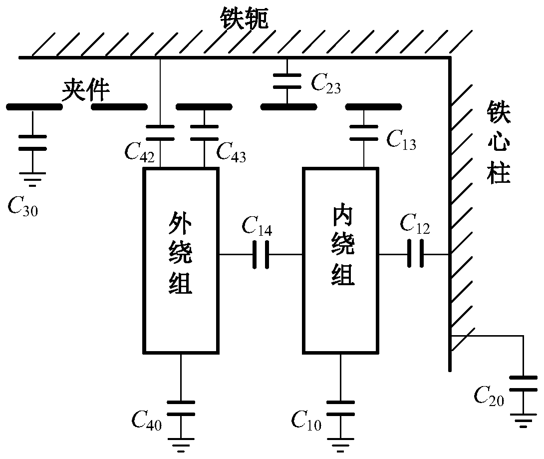
However, for large-scale power transformers, the insulation structure between the winding and the core and the clamp is relatively complex, and the insulation of each part is relatively independent and there is a complex capacitive coupling effect. In most cases, the insulation of the relatively small capacitance is defective. It will be difficult to respond to the traditional wiring method. Simply grounding the core and clamps often cannot effectively reflect the real situation of the insulation of each part.

Method used


Image

  • Transformer insulation defect analysis method based on partial dielectric loss test
  • Transformer insulation defect analysis method based on partial dielectric loss test
  • Transformer insulation defect analysis method based on partial dielectric loss test

Examples


Embodiment

[0030] A transformer insulation defect analysis method based on partial dielectric loss test, which includes:

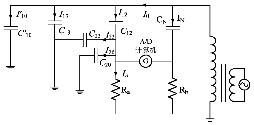
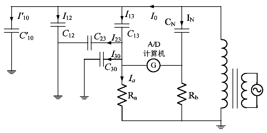
[0031] a) Use the positive connection method to test the dielectric loss between the transformer winding-core (clamp grounded or shielded), winding-clamp (core grounded or shielded), and obtain the winding pair when the core / clamp is grounded respectively. Dielectric loss and capacitance test values ​​of clip / core;

[0032] b) Analyze the electric field coupling effect between the insulation media of transformer windings, iron cores, and clamps, and test the dielectric loss and mutual The difference determines the actual difference in the specific dielectric loss of the insulation between the windings, clamps and core parts, and excludes the coupling effect between the insulating parts and the influence of the capacitance of each insulating part on the test results;

[0033] c) Combining with the typical structure of a large power transformer, according to the corre...


PUM


Abstract

The invention discloses a transformer insulation defect analysis method based on a partial dielectric loss test. The dielectric loss test is widely applied to the analysis and diagnosis work of a transformer insulation state, but a traditional dielectric loss test method only tests the dielectric loss of a winding-iron core / a clamp / ground, and due to the fact that a negative method of wiring is usually adopted due to the limitation that a main transformer is grounded, the test accuracy is poor, and defects of a specific position cannot be effectively judged. According to a typical structure ofa large power transformer, partial testing is carried out on the dielectric loss between the transformer winding-iron core, winding-clamp and different windings by using a method of positive wiring for reducing the voltage, and combined with the analysis of an electric field coupling effect between various partial insulating media, accurate analysis and defect positioning are carried out on insulation defects between various components of a transformer. The transformer insulation defect analysis method proposed by the invention has higher defect detection efficiency and positioning accuracy.

Description

technical field [0001] The invention relates to the diagnosis of transformer insulation defects, in particular to a method for detecting and diagnosing insulation defects of transformer windings, iron cores and clips based on partial dielectric loss testing. Background technique [0002] As an important item in transformer handover, pretest, routine and diagnostic tests, dielectric loss and capacitance tests are of great significance for judging the overall dampness of transformer insulation, oil quality deterioration, and serious local defects between windings. However, different wiring methods have a great influence on the test results of dielectric loss capacitance. Standards such as DL / T474.3-2006 "Guidelines for Implementation of On-Site Insulation Tests" and JB / T501-2006 "Guidelines for Testing Power Transformers" all stipulate that the iron core and clamp should be short-circuited to ground during the test. When taking the insulation between the winding and the core,...

Claims


Application Information

Patent Timeline
Patent Type & Authority Applications(China)
IPC IPC(8): G01R31/14G01R31/12G01R27/26
CPCG01R27/2605G01R27/2688G01R31/1227G01R31/14
Inventor 詹江杨姚晖张帆何文林李晨孙翔梅冰笑刘浩军邵先军王文浩杨智郑一鸣陈珉孙林涛徐龙陈易浩刘丰文魏泽民
Owner ELECTRIC POWER RES INST OF STATE GRID ZHEJIANG ELECTRIC POWER COMAPNY
Learn More