
A special-shaped three-dimensional shock-isolation bearing

A vibration isolation bearing, special-shaped three-dimensional technology, applied in the fields of environmental vibration, earthquake resistance, and shock absorption, can solve the problems that the performance of the isolation bearing is not stable enough, affect the isolation effect of the vibration isolation bearing, and the production cost is high, and achieve an increase in effective Bearing area, small occupied space, and the effect of improving torsion resistance

Active Publication Date: 2021-08-31
SHANGHAI UNIV +1
View PDF19 Cites 0 Cited by
  • Summary
  • Abstract
  • Description
  • Claims
  • Application Information

AI Technical Summary

Problems solved by technology

One is to use air springs and hydraulic oil for vertical vibration isolation, but the performance of this vibration isolation support is not stable enough
The other type is a combined seismic isolation bearing that converts the vertical deformation into the horizontal displacement of the bearing. Although the performance is relatively stable, the size is large and the manufacturing cost is high. The large shear deformation of the isolation bearing will affect the isolation effect of the isolation bearing under the earthquake, and cannot effectively solve the problem of performance matching between the bearing capacity and deformation capacity of the isolation bearing

Method used


Image

  • A special-shaped three-dimensional shock-isolation bearing
  • A special-shaped three-dimensional shock-isolation bearing
  • A special-shaped three-dimensional shock-isolation bearing

Examples


Embodiment 1

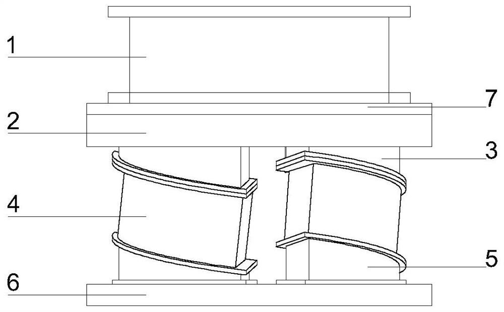
[0054] see Figure 1 to Figure 5 , the special-shaped three-dimensional shock-isolation bearing of the present invention is located between the upper and lower structures that require shock-isolation, and it includes:

[0055]A bottom plate (6) connected to the lower structure; at least two special-shaped supports (4), composed of parallel upper and lower sealing plates sandwiching the first elastic block; the upper connecting corner block and the lower connecting corner block (3 and 5) has a horizontal bottom surface and an inclined top surface, and when the upper connecting corner block is inverted and the lower connecting corner block is superimposed, the bottom surfaces of the two are parallel; a horizontal support (1), the second elastic block is clamped by the upper and lower plates Consists of: a sliding panel (2); the upper connecting corner block (3) is inverted and sequentially connected with the special-shaped support (4) and the lower connecting corner block (5), a...

Embodiment 2

[0060] see Image 6 and Figure 7 The difference between the second embodiment and the first embodiment is that the special-shaped support is pretreated and pre-deformed so that the upper connecting corner block (3) is inverted and sequentially connected with the special-shaped support (4) and the lower connecting corner block (5). Together, the special-shaped support (4) is placed obliquely relative to the contact slope with the upper and lower connecting corner blocks, and the three are in a vertical state, and the special-shaped three-dimensional shock-isolation support has a regular cylindrical space structure as a whole. The pre-deformation treatment enhances the deformation ability of the special-shaped three-dimensional seismic isolation bearing.

[0061] When the special-shaped support (4) is not pre-deformed, its shape is a spatial winding structure; after the special-shaped support (4) is pre-deformed, its shape is a regular cylindrical space structure.

Embodiment 3

[0063] see Figure 8 , Figure 9 , Figure 10 and Figure 11 The difference between embodiment three and embodiment two is that: for the special-shaped support 4 that adopts pre-deformation treatment, an upright tubular sleeve 9 is fixed on the center of the bottom plate (6), and a columnar rotating guide rail 8 is inserted therein. The upper end of the rotating guide rail 8 passes through the central hole opened by the sliding panel 2 and then touches the bottom of the horizontal support 1. The contact surfaces of the rotating guide rail 8, the horizontal support 1 and the sliding panel 2 are all made of friction materials, and the friction coefficient is within a certain range. change, and place damping material between the rotating rail 8 and the sleeve 9 at the same time. The combined structure of the rotating guide rail (8) and the sleeve (9) acts as a horizontal limit for the special-shaped support (4), and at the same time, a damping material can be placed between th...


PUM


Abstract

A special-shaped three-dimensional shock-isolation support, which is located between the upper and lower structures that require shock isolation, including: a bottom plate connected to the lower structure; at least two special-shaped supports, composed of parallel upper and lower sealing plates sandwiching a first elastic block ; The upper and lower connecting corner blocks have a horizontal bottom surface and an inclined top surface, and when the upper connecting corner block is inverted and superimposed on the lower connecting corner block, the bottom surfaces are parallel; the horizontal support is composed of the upper and lower plates sandwiching the second elastic block ; sliding panel; the upper connecting corner block is connected with the special-shaped support and the lower connecting corner block upside down in turn, and then fixed and supported on the bottom plate in a center-symmetrical distribution, and the sliding panel is fixed on the bottom surface of the inverted upper connecting corner block, The horizontal support is supported on the sliding panel vertically and rotatably around the central symmetry line, and the contact surface is made of friction material, and the upper plate of the horizontal support is connected with the upper structure. The invention can isolate horizontal and vertical earthquakes at the same time, and can be used for vertical earthquake isolation of buildings with large self-weight.

Description

technical field [0001] The invention relates to the technical fields of environmental vibration and shock resistance and shock absorption, in particular to a special-shaped three-dimensional shock-isolation bearing, which can be used for shock / vibration reduction of ordinary buildings, special structures, bridges, and mechanical equipment. Background technique [0002] The seismic isolation technology of building structure foundation has achieved remarkable research results. However, research results at home and abroad show that the isolation elements commonly used at present can only isolate horizontal earthquakes, and have no isolation effect on vertical earthquakes. In high-intensity areas where the vertical seismic action is relatively large, the vertical seismic action may become the main controlling factor of the structural response. Furthermore, for some important equipment and buildings, such as nuclear power structures, vertical earthquakes will bring great hidden ...

Claims


Application Information

Patent Timeline
Patent Type & Authority Patents(China)
IPC IPC(8): E04B1/36E04B1/98E04H9/02E01D19/04F16F15/02F16F15/04
CPCE01D19/041E04B1/36E04H9/021E04H9/022F16F15/02F16F15/022F16F15/04
Inventor 刘文光张杰李韶平王晓雯王凯
Owner SHANGHAI UNIV
Learn More