
Lifting frame for fast adjustment of to-be-tested area of detonation schlieren

A technology of the area to be tested and the lifting frame, which is applied in the field of lifting frames, can solve the problems of limited height adjustment range, uncertain adjustment range, and increased experimental cost, and achieve the effects of convenient operation, wide adaptability, and simple structure

Active Publication Date: 2019-07-19
NORTHWESTERN POLYTECHNICAL UNIV
View PDF5 Cites 0 Cited by
  • Summary
  • Abstract
  • Description
  • Claims
  • Application Information

AI Technical Summary

Problems solved by technology

First of all, the detonation chamber will generate thrust and slide when it is working, and the table top of the lifting table is mostly smooth, so an additional set of fixtures must be ordered to fix the two, which will greatly increase the cost of the experiment; secondly, for a certain size The height adjustment range of the lifting table is limited (for example, the adjustment range corresponding to the size of the 20×20cm table is generally not more than 30cm), which may not meet the adjustment range required by the experiment; in addition, the detonation chamber is generally placed horizontally on the lifting table, which means When adjusting the area to be tested, it is necessary to move the detonation chamber in the horizontal direction, so the vertical lifting performance of the lifting platform will be useless
Throughout the research at home and abroad, there is still no mechanism that is particularly suitable for the rapid adjustment of the knocking schlieren area to be tested. Therefore, a lifting frame with a simple structure, low cost, and a wide range of application is designed. The smooth development of the schlieren experiment is of great significance

Method used


Image

  • Lifting frame for fast adjustment of to-be-tested area of detonation schlieren
  • Lifting frame for fast adjustment of to-be-tested area of detonation schlieren
  • Lifting frame for fast adjustment of to-be-tested area of detonation schlieren

Examples


Embodiment Construction

[0020] The present invention will be further described below in conjunction with the accompanying drawings and the specific implementation process.

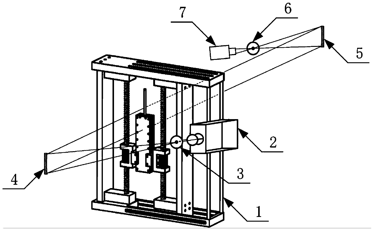
[0021] see figure 1 , before carrying out the schlieren measurement, first adjust the centers of the light source 2, the small hole 3, the first concave mirror 4, the second concave mirror 5, the knife edge 6, the high-speed camera 7 and other components to the same height to ensure that the first concave mirror 4 The reflected parallel light can just be completely projected onto the second concave mirror 5, and the angle between the light between the small hole 3 and the first concave mirror 4 and the light between the first concave mirror 4 and the second concave mirror 5 Keep within a small range of 10-20° to improve the shooting effect of schlieren images. The detonation chamber 1-17 (clamped by the lifting frame 1) is placed in the parallel light between the first concave mirror 4 and the second concave mirror 5 In this way...


PUM


Abstract

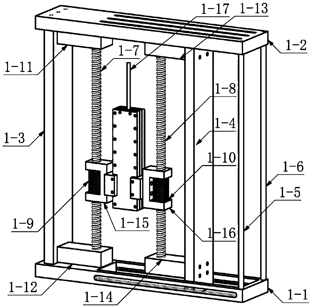
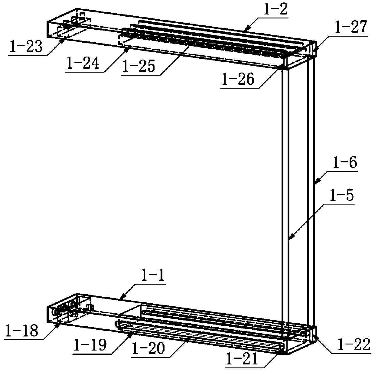
The invention provides a lifting frame for fast adjustment of a to-be-tested area of a detonation schlieren and belongs to the field of schlieren experiment devices. The lifting frame comprises a base, a top plate, a fixing supporting assembly, a sliding assembly, a supporting column assembly, a clamp assembly, adjusting screw rods and adjusting screw nuts, wherein a square through hole and a square groove which are matched with the fixing supporting assembly and the sliding assembly are designed in the base and the top plate correspondingly; the fixing supporting assembly and the supporting column assembly serve as force-bearing parts to support the lifting frame; the sliding assembly can perform large-stroke sliding according to the actual size of a detonation chamber; the two adjustingscrew rods are fixed to the fixing supporting assembly and the sliding assembly correspondingly; the clamp assembly and the adjusting screw nuts are assembled while the clamp assembly clamps the detonation chamber; and the detonation chamber can be driven to slide together by rotating the adjusting screw nuts, and thus fast adjustment of the position of the to-be-tested area is achieved. By meansof the lifting frame for fast adjustment of the to-be-tested area of the detonation schlieren, the problems that an existing lifting table is difficult to fix, and the adjusting range and the size supporting range of the detonation chamber are limited can be solved, and support is provided for smoothly carrying out detonation schlieren experiment.

Description

technical field [0001] The invention relates to a lifting frame that can quickly adjust the area to be tested in a detonation chamber when the schlieren technique is used to study the propagation process of the detonation wave, and belongs to the field of schlieren experimental devices. Background technique [0002] In the field of detonation research, schlieren is one of the most commonly used optical measurement methods. On the one hand, it is attributed to the simple structure and low cost of the schlieren system. On the other hand, it can directly display the interaction of shock waves in the process of flame propagation. The process helps researchers to understand the mechanism of knock formation. [0003] The common layout of the schlieren system is "Z" shape, that is, the point light source is reflected by the first concave mirror to form parallel light, passes through the area to be tested, and then reflects from the second concave mirror through the knife edge, and ...

Claims


Application Information

Patent Timeline
Patent Type & Authority Applications(China)
IPC IPC(8): B25B11/00B25H1/10
CPCB25B11/00B25H1/10
Inventor 范玮郑家炜贾文杰夏壹斌唐慧
Owner NORTHWESTERN POLYTECHNICAL UNIV
Learn More