Automatic pop-rivet drilling device for door plate

A door panel, drilling position technology, applied in other manufacturing equipment/tools, manufacturing tools, etc., can solve the problems of unguaranteed safety production, high manufacturing cost, low production efficiency, etc., and achieves excellent practicability and economy. Design flexibility and produce efficient effects

Pending Publication Date: 2019-07-19
陈俊才 +1
View PDF0 Cites 4 Cited by
  • Summary
  • Abstract
  • Description
  • Claims
  • Application Information

AI Technical Summary

Problems solved by technology

At the same time, in the existing production process of drilling and pulling nails for elevator door panels, it is completely manual drilling and pulling nails. cost is also high

Method used


Image

  • Automatic pop-rivet drilling device for door plate
  • Automatic pop-rivet drilling device for door plate
  • Automatic pop-rivet drilling device for door plate

Examples


Embodiment

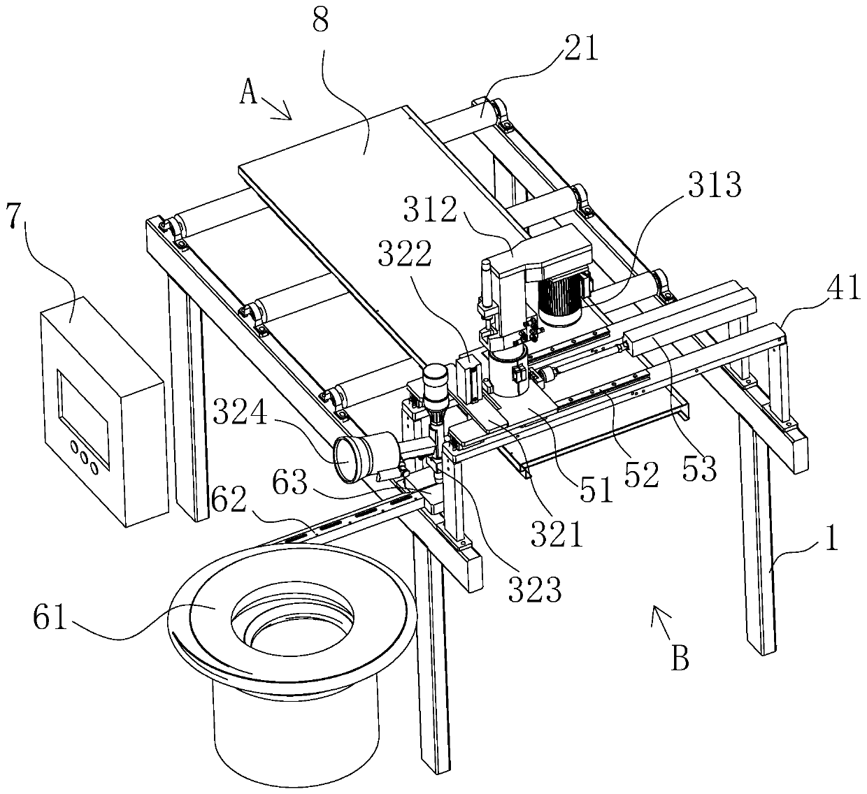
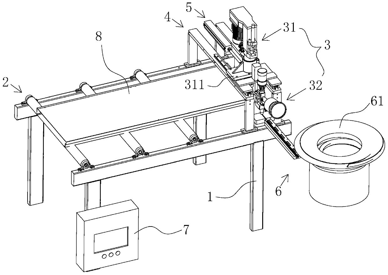
[0043] Such as Figure 1-2 As shown, the preferred automatic drilling and pulling nail device for door panels provided in this embodiment includes: the machine base 1 is provided with a conveying roller platform 2 which is driven by a roller 21 to transport the workpiece door panel, and one end of the machine base 1 is set on the conveying roller The upper end of the table 2 is the feed inlet A, the other end of the machine base 1 where the crossbeam installation mechanism 4 is set is the discharge outlet B, and the crossbeam installation mechanism 4 is provided with two crossbeam brackets 41 erected on the upper end of the machine base 1 side, so that the crossbeam Between the brackets 41, there is a working space arranged on the upper end of the machine base 1 to provide the drilling mechanism 31 and the nail pulling mechanism 32, and the pushing mechanism 5 cooperates to realize drilling and pulling the nails. In the action space set between the two beam brackets 41 , the d...


PUM


Abstract

The invention discloses an automatic pop-rivet drilling device for a door plate. The automatic pop-rivet drilling device comprises a machine base, wherein the machine base is equipped with a conveyingroller table and a pop-rivet drilling mechanism; a beam mounting mechanism is arranged on the machine base for providing operation space of the pop-rivet drilling mechanism and a pushing mechanism; the pushing mechanism is connected to the pop-rivet drilling mechanism to provide transverse moving power; the pop-rivet conveying mechanism is arranged for orderly arranging and conveying pop-rivets according to a predetermined shape to the pop-rivet drilling mechanism for later use; under control of the control system, the conveying roller table is used for conveying a workpiece door plate to a predetermined drilling position for allowing the pop-rivet drilling mechanism to perform lifting drilling on the workpiece door plate, and then, the pop-rivet drilling mechanism is used for taking rivets for later use from the pop-rivet conveying mechanism, and moving the rivets to a predetermined drilling position for inserting sucked pop-rivets onto the predetermined drilling position, and simultaneously performing pop-rivet riveting operation. The automatic pop-rivet drilling device realizes quick and efficient arranging for pop-rivets for door plate drilling by automatic drilling and pop-rivet riveting, so that safe production and efficient operation are realized.

Description

technical field [0001] The invention relates to the technical field of automatic production of elevators, in particular to an automatic drilling, riveting and riveting device for door panels. Background technique [0002] In the design and manufacture process of elevator hall door door panels, in order to reduce manufacturing costs and improve the aesthetics of the door panels, a layer of stainless steel plate is usually covered on the bottom plate of iron elevator door panels, and then holes are drilled on the overlapping bottom plate and stainless steel plate, and then Riveted with aluminum pull studs. At the same time, in the existing production process of drilling and pulling nails for elevator door panels, it is completely manual drilling and pulling nails. The cost is also high. In order to solve this problem, it is necessary to design an automatic drilling and pulling device to replace the existing manual production method. Contents of the invention [0003] (1) ...

Claims


Application Information

Patent Timeline
Patent Type & Authority Applications(China)
IPC IPC(8): B23P23/04B21J15/10
CPCB21J15/10B23P23/04
Inventor 陈俊才黄胜光毛永雄刘玉乔
Owner 陈俊才
Why Eureka
Try Eureka