
Cold application patch and production device thereof

A production device and cold compress technology, applied in lamination devices, layered products, and other household appliances, can solve the problems of cumbersome processing and high production costs, and achieve the effect of reducing operation process, reducing processing flow, and reducing use

Pending Publication Date: 2019-07-19
安徽省纳胜生物科技有限公司
View PDF0 Cites 6 Cited by
  • Summary
  • Abstract
  • Description
  • Claims
  • Application Information

AI Technical Summary

Problems solved by technology

[0004] Aiming at the deficiencies of the prior art, the object of the present invention is to provide a cold compress and its production device, which solves the technical problems of high production cost and cumbersome processing in the prior art.

Method used


Image

  • Cold application patch and production device thereof
  • Cold application patch and production device thereof
  • Cold application patch and production device thereof

Examples


Embodiment 1

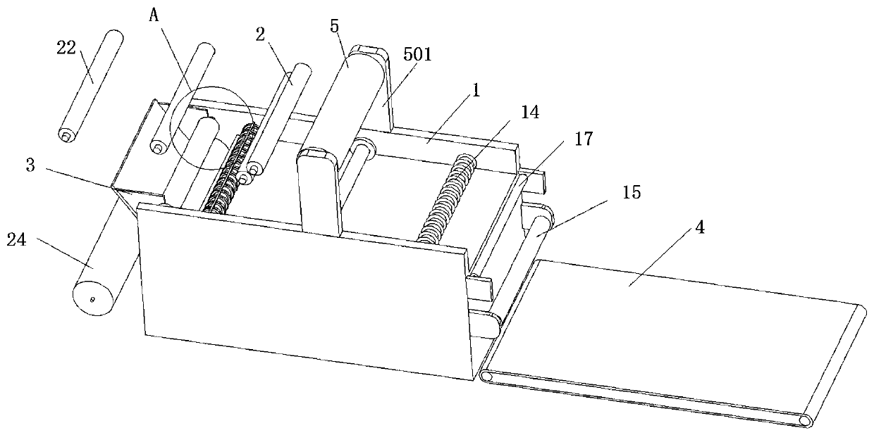
[0048] like figure 1 As shown, this embodiment provides a production device for cold compresses, including a machine base body 1 , a separation mechanism 2 , and a feeding mechanism 3 ; the left side of the machine base body 1 is provided with a transmission mechanism 6 .

[0049] Supports 501 are arranged on both sides of the frame body 1, and an unwinder 5 is fixed on the upper part of the support 501. The unwinder 5 rolls the backing tape into the separation mechanism 2, and the separation mechanism 2 separates the backing tape. There are two parts: the upper non-woven glue coating layer 901 and the lower isolation layer 902.

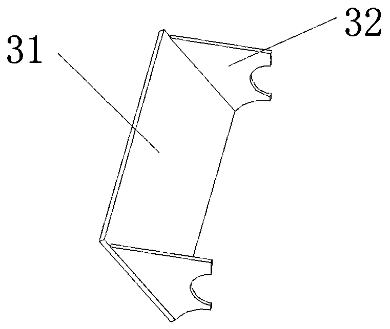
[0050] like figure 2 As shown, one end of the base body 1 is provided with a feeding mechanism 3, including a baffle plate 31 and a support plate 32. The bottom of the support plate 32 fits with the surface where the driving roller 11 and the pressure roller 12 are located, and is arranged on both sides. Side position, the baffle plate 31 is obli...

Embodiment 2

[0060] like Figure 8-9 As shown, this embodiment provides a production device for cold compresses, including a machine base body 1, a separation mechanism 2, and a feeding mechanism 3. The structure and working principle of its components are the same as those in Embodiment 1. The upper part of the machine base body 1 is fixed by There is a first unwinding machine 51, a second unwinding machine 52 is fixed on the side, and an unwinding roller 24 is arranged at the bottom of the machine base body 1; the first unwinding machine 51 rolls the backing adhesive tape into the separation mechanism 2, And the backing tape is separated into two parts, the lower isolation layer 902 and the upper non-woven adhesive layer 901.

[0061] One end of the base body 1 is provided with a feeding mechanism 3, the bottom is provided with a pressure roller 12, and the bottom of the pressure roller 12 is provided with a driving roller 11, and the upper end surface of the base body 1 is provided with...


PUM


Abstract

The invention discloses a cold application patch and a production device thereof. The device comprises a machine base body, a separation mechanism and a feeding mechanism; an unreeling machine is fixed at the upper part of the machine base body, and the unreeling machine separates a backing adhesive tape into an upper non-woven fabric gluing layer and a lower isolating layer; and the feeding mechanism is arranged at one end part of the machine base body, a driving roller is arranged below the feeding mechanism, and a pressing roller, an embossing roller and a cutter roller are sequentially arranged on the upper end surface of the machine base body from right to left. In the device, the backing adhesive tape is directly divided into an upper part and a lower part, a hydrogel layer is arranged between the upper layer and the lower layer of the backing adhesive tape, the upper part and the lower part of the backing adhesive tape are pressed and laminate by the pressing roller, and segmented cutting is carried out, so that a single block-shaped cold application patch structure is formed; and the whole device realizes one-step synthesis of the cold compress paste from raw material processing to cutting, so that the production efficiency is greatly improved.

Description

technical field [0001] The invention belongs to the technical field of cold compresses, and in particular relates to a cold compress and a production device thereof. Background technique [0002] Hydrogel cold compress is made of sodium polyacrylate hydrogel as the main raw material. It is a new type of patch that has recently emerged in my country, such as: antipyretic patches, various cold patches, hot compresses, beauty patches, etc. Compared with traditional plasters, hydrogel cold compresses have better transdermal effects, high biopharmaceutical utilization, non-irritating, good air permeability, convenient use, and less allergies. For this reason, domestic production has increased year by year in recent years. [0003] However, because the hydrogel is not viscous enough, it is easy to fall off when it is attached to the skin, especially the joints, and it cannot be made into a coil like hot melt adhesive and die-cut into a finished product. Therefore, the current prod...

Claims


Application Information

Patent Timeline
Patent Type & Authority Applications(China)
IPC IPC(8): A61F7/02C08J3/075C08L33/02C08L1/28C08L39/06C08K3/22B32B5/02B32B27/40B32B27/36B32B27/32B32B13/14B32B13/12B32B13/08B32B13/04B32B29/00B32B33/00B32B37/10B32B38/00B32B38/10B32B38/06
CPCA61F7/02C08J3/075B32B5/022B32B27/40B32B27/36B32B27/32B32B13/14B32B13/12B32B13/08B32B13/04B32B29/00B32B33/00B32B37/10B32B38/0004B32B38/10B32B38/06A61F2007/0219A61F2007/0261A61F2007/0098C08J2333/02C08J2401/28C08J2439/06C08K2003/2241B32B2535/00B32B2555/00
Inventor 李华段秋芬
Owner 安徽省纳胜生物科技有限公司
Learn More