Rotor chip, rotor and motor

A chip and rotor technology, applied in the field of rotors and motors, can solve the problems of weakening cogging effect, improving torque fluctuation, weakening cogging effect, complex production process, etc., to improve the distribution of magnetic force lines, reduce the time of insertion, and simplify production Process effect

Pending Publication Date: 2019-07-16
GUANGDONG JINBA INTELLIGENT TECHNOLOGY CO LTD
View PDF0 Cites 5 Cited by
  • Summary
  • Abstract
  • Description
  • Claims
  • Application Information

AI Technical Summary

Problems solved by technology

At present, there is a power motor with a 48-slot stator and an 8-pole rotor. In order to improve the torque fluctuation of the power motor, there are two common methods; They are all staggered by a small angle along a certain direction, so that the winding slots of the stator are offset by a certain angle in the axial direction, so as to weaken the cogging effect and improve the torque fluctuation. In this way, in the process of making the motor, each The stator chips are all staggered by a small angle, so the production process is more complicated and the production cost is often higher; the other is the form of rotor chute, that is, the rotor core is set into several sections, and the gap between each section of the rotor core is They are all staggered by a certain angle, and each section of the rotor core is respectively inserted with a magnetic steel block, so that the magnetic steel blocks on each section of the rotor are staggered by a certain angle, so as to achieve the purpose of weakening the cogging effect and improving the torque fluctuation. Method Since each segment of the rotor core needs to be inserted with magnetic steel blocks, the number of magnetic steel blocks is the number of magnetic steel slots on a single rotor chip multiplied by the number of segments set in the rotor core, so the number of magnetic steel blocks is large, and It is also necessary to make the rotor composed of rotor chips form several sections with staggered angles, so the production process is relatively complicated and the production cost is also high

Method used


Image

  • Rotor chip, rotor and motor
  • Rotor chip, rotor and motor
  • Rotor chip, rotor and motor

Examples


Embodiment Construction

[0019] The idea, specific structure and technical effects of the present invention will be clearly and completely described below in conjunction with the embodiments and accompanying drawings, so as to fully understand the purpose, scheme and effect of the present invention. It should be noted that, in the case of no conflict, the embodiments in the present application and the features in the embodiments can be combined with each other.

[0020] It should be noted that, unless otherwise specified, when a feature is called "fixed" or "connected" to another feature, it can be directly fixed and connected to another feature, or indirectly fixed and connected to another feature. on a feature. In addition, descriptions such as up, down, left, right, front, and back used in the present invention are only relative to the mutual positional relationship of the components of the present invention in the drawings.

[0021] Also, unless defined otherwise, all technical and scientific ter...


PUM


Abstract

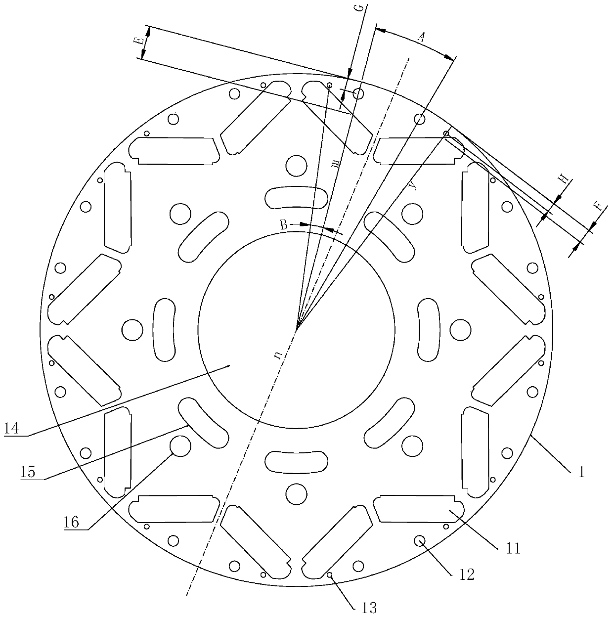
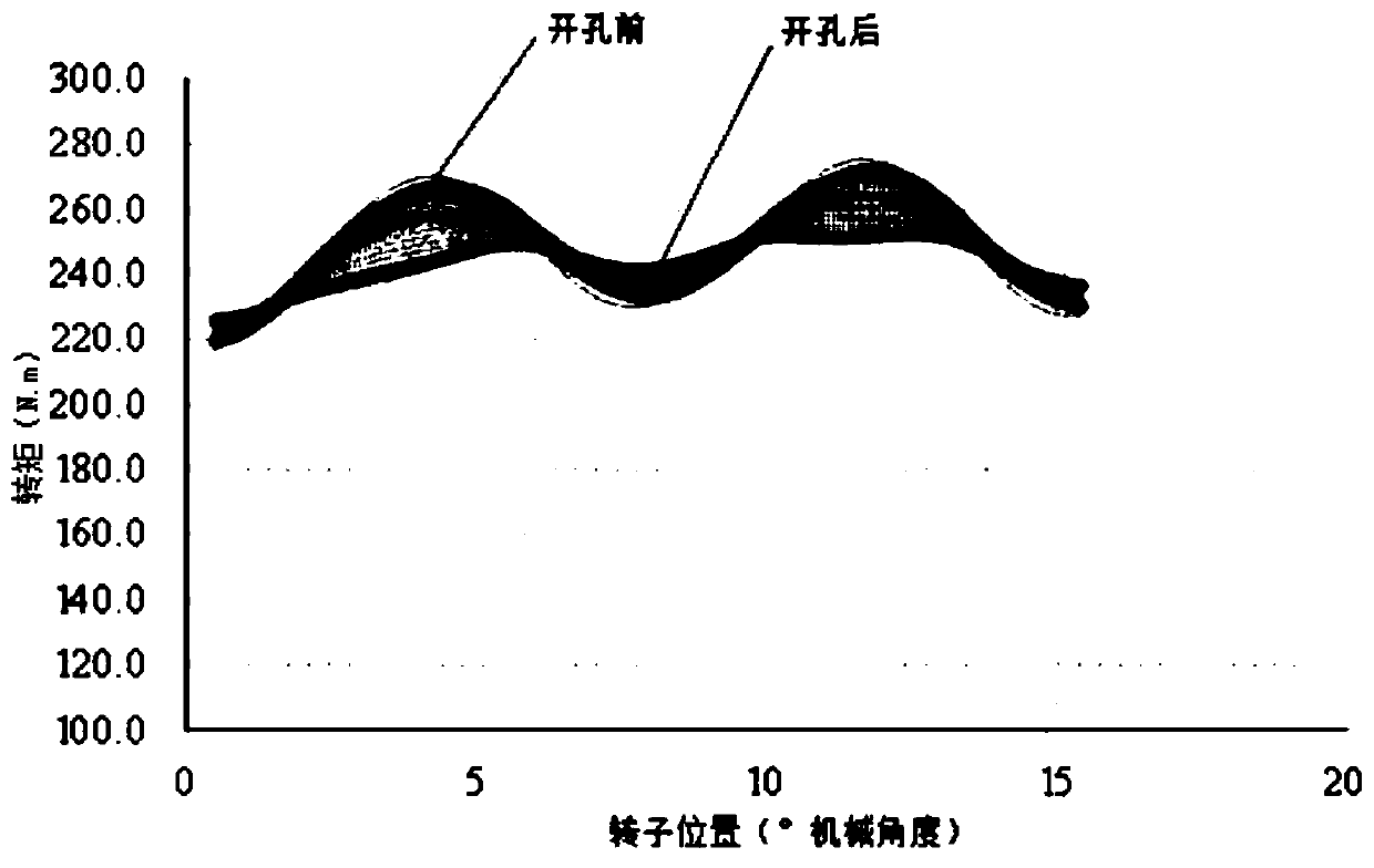
The invention discloses a rotor chip, a rotor and a motor. The rotor chip comprises a disc-shaped chip, wherein the chip is provided with 16 magnetic steel grooves, and every two adjacent magnetic steel grooves form a set of magnetic groove pairs; the two magnetic steel grooves in each group of magnetic groove pairs are arranged in a V shape, and the opening direction faces the outer side of the chip; the eight groups of magnetic groove pairs are symmetrically distributed around the center of the chip; the two magnetic steel grooves in the same group of magnetic groove pairs are symmetricallyarranged relative to the straight line n which passes through the center of a certain chip; the chip is provided with a group of magnetic separation holes in the V-shaped opening side of each group ofmagnetic grooves; the magnetic separation hole group comprises two first magnetic separation holes and two second magnetic separation holes which are symmetrically arranged relative to the straight line n; and the second magnetic separation holes are located in the two sides of the first magnetic separation holes. The distribution of magnetic force lines of the rotor adopting the rotor chip can be effectively improved, so that the tooth groove effect of the motor is weakened, and the purpose of improving the torque fluctuation is achieved; and in addition, the structure of a stator inclined groove and a rotor inclined groove does not need to be arranged, so that the production process is simplified, and the cost is lowered.

Description

technical field [0001] The invention relates to the technical field of motors, in particular to a rotor chip, a rotor and a motor with the rotor chip. Background technique [0002] The power motor used in electric vehicles has high requirements on the output torque fluctuation. If the torque fluctuation is large, the driving comfort and ride comfort of the car will deteriorate. Therefore, a small torque fluctuation is an important indicator to measure the power motor. At present, there is a power motor with a 48-slot stator and an 8-pole rotor. In order to improve the torque fluctuation of the power motor, there are two common methods; They are all staggered by a small angle along a certain direction, so that the winding slots of the stator are offset by a certain angle in the axial direction, so as to weaken the cogging effect and improve the torque fluctuation. In this way, in the process of making the motor, each The stator chips are all staggered by a small angle, so th...

Claims


Application Information

Patent Timeline
IPC IPC(8): H02K1/27
CPCH02K1/276H02K2213/03
Inventor 林楚辉李拥军师海风
Owner GUANGDONG JINBA INTELLIGENT TECHNOLOGY CO LTD
Why Eureka
Try Eureka