A Phase Center Measurement Method for Broadband Antenna with Symmetrical Main Beam

A technology of phase center and broadband antenna, which is applied in direction finders using radio waves, antenna radiation patterns, radio wave direction/deviation determination systems, etc., which can solve the problem of heavy testing workload and difficulty in determining the exact position of the phase center of the antenna under test , The problem of not wide adaptability, etc., achieve the effect of not demanding test conditions, reducing the test workload and simplifying the test process

Active Publication Date: 2021-05-04
SOUTHWEST CHINA RES INST OF ELECTRONICS EQUIP
View PDF6 Cites 0 Cited by
  • Summary
  • Abstract
  • Description
  • Claims
  • Application Information

AI Technical Summary

Problems solved by technology

In fact, there are still some public documents that introduce various improvement measures for the phase center measurement method of the GNSS receiving antenna. Although there are differences in the specific data processing and analysis, the overall method flow is basically the same. Here no more introductions
[0015] From the above-mentioned summary of current antenna phase center measurement methods, it can be seen that: Type ① The traditional method of determining the antenna phase center through phase pattern testing is relatively standard in operation, but it requires turntables and other supporting equipment, and the test workload is relatively large
Although the second type is based on the three-antenna method and obtains the change law of the phase center of the antenna in the ultra-wide frequency band through six S-parameter measurements, but this method can only determine the relative change of the phase center of the broadband antenna, and it is difficult to determine the antenna under test. The exact location of the phase center
The third type of method is a special method for special objects, especially for the measurement of the phase center of the GNSS global satellite navigation receiving antenna, many unique methods are proposed. This type of method is very targeted and not widely applicable.
From the above three types of methods, the accurate measurement of the phase center of the broadband electronic reconnaissance receiving antenna can use the traditional method based on the phase pattern, but without the assistance of the turntable and other equipment, the phase pattern cannot be obtained accurately, thus limiting use of traditional methods

Method used


Image

  • A Phase Center Measurement Method for Broadband Antenna with Symmetrical Main Beam
  • A Phase Center Measurement Method for Broadband Antenna with Symmetrical Main Beam
  • A Phase Center Measurement Method for Broadband Antenna with Symmetrical Main Beam

Examples


Embodiment Construction

[0031] The present invention will be further described below in conjunction with the accompanying drawings.

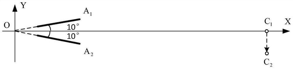
[0032] Two tested antennas of the same type are marked as A 1 with A 2 , the previous intersection point where the beam axis passes through the outer envelope space of the antenna entity is denoted as F 1 with F 2 , and the next intersection point is denoted as B 1 with B 2 , obviously the line segment F 1 B 1 Located on Antenna A 1 On the beam axis, the line segment F 2 B 2 Located on Antenna A 2 on the beam axis. Since the antenna under test has the characteristic of main beam symmetry, the antenna A 1 The phase center point of should be located on the line segment F 1 B 1 On, Antenna A 2 The phase center point of should be located on the line segment F 2 B 2 , the details of its phase center point will be determined according to the following steps. Antenna A 1 with A 2 The working frequency band is [f down ,f up ], the test frequency f 0 ∈[f ...


PUM


Abstract

The invention relates to the technical field of electronic reconnaissance direction finding applications, and discloses a phase center measurement method of a broadband antenna with a symmetrical main beam. Establish a two-dimensional rectangular coordinate plane so that the two beam axes are in the coordinate plane, and the two beam axes are symmetrical about one coordinate axis, and the extension line of the two beam axes intersects the coordinate origin; take a point C on the coordinate axis as the axis of symmetry 1 , so that point C 1 are located in the far-field region of both antennas; at point C 1 place frequency f at 0 The radiation source, measure the phase difference φ of the received signal 1 ; will be at point C 1 The radiation source moves in the coordinate plane along the direction perpendicular to the coordinate axis to C 2 point, calculate the radiation source from C 1 move point to C 2 The phase difference change value φ caused after the point 0 ; according to the phase difference change value φ 0 , calculate the coordinate position of the phase center of the antenna under test. The method does not require equipment such as a turntable, has low test conditions, simple test steps and high test efficiency, and provides a new test method for the phase center measurement of broadband antennas commonly used in electronic reconnaissance.

Description

technical field [0001] The invention relates to the technical field of electronic reconnaissance and direction finding applications, in particular to a method for measuring the phase center of a broadband antenna with a symmetrical main beam. Background technique [0002] The electromagnetic wave radiated by the main beam of the antenna can be approximated as radiating from an ideal point source. If the phases of the far-field signal are equal to the equidistant from the point, then the point can be defined as the "phase center" of the antenna. point" (or simply "phase center"). The phase center of the antenna has an important influence on the direction finding application of the interferometer based on the phase comparison method in electronic reconnaissance, because in this direction finding application, multiple broadband unit antennas are used to form an antenna array to form an interferometer, and the electromagnetic target radiation The incoming wave direction of the ...

Claims


Application Information

Patent Timeline
Patent Type & Authority Patents(China)
IPC IPC(8): G01R29/10G01S3/14
CPCG01R29/10G01S3/14
Inventor 石荣何涛王沙飞
Owner SOUTHWEST CHINA RES INST OF ELECTRONICS EQUIP
Why Eureka
Try Eureka