
A switched reluctance generator converter system

A technology of switched reluctance and generators, which is applied in the direction of controlling generators, controlling generators through magnetic field changes, and controlling systems. It can solve problems such as complicated control, complicated structure and control, and decreased system efficiency, achieving structural and The control method is simple, the effect of enhancing the excitation effect and enhancing the power generation capacity

Active Publication Date: 2020-09-11
浙江知多多网络科技有限公司
View PDF9 Cites 0 Cited by
  • Summary
  • Abstract
  • Description
  • Claims
  • Application Information

AI Technical Summary

Problems solved by technology

[0005] In terms of changing the excitation voltage and current in the excitation stage, some changes have been made in the industry in recent years from the structure of the converter and the control method. When the excitation power comes from the battery, it is beneficial to improve the current stability of the converter system. , but the battery power is easy to run out, so there are some examples in the industry that use the electric energy generated by the switched reluctance generator itself to feed back the battery to charge the battery. However, when the load on the output side of the power generation is too large, or the typical wind power condition When the grid is connected to the grid due to excessive load voltage drop and low voltage ride-through, even a fully charged battery is helpless and cannot reversely supply power to the load side, but even if it can supply power, the voltage required for excitation is often lower than the power generation voltage. Therefore, it is difficult to directly use the battery to feed back to the load side, or to separately design a boost converter to increase the voltage, which will inevitably increase the cost and complicate the structure and control.
[0006] For the converter system, the switching loss of the switching tube, especially when the high-frequency switching is working, is a problem that cannot be ignored in the entire power generation system, which makes the efficiency of the system decrease, the problem of heat generation is prominent, and the reliability is low. The conventional method in the industry is to use Soft switching technology, but it will inevitably make the structure more complicated and the control complicated. Therefore, the simple structure of the switch tube and the low switching loss of the simple control mode are the development direction of the power electronics industry.

Method used


Image

  • A switched reluctance generator converter system

Examples


Embodiment Construction

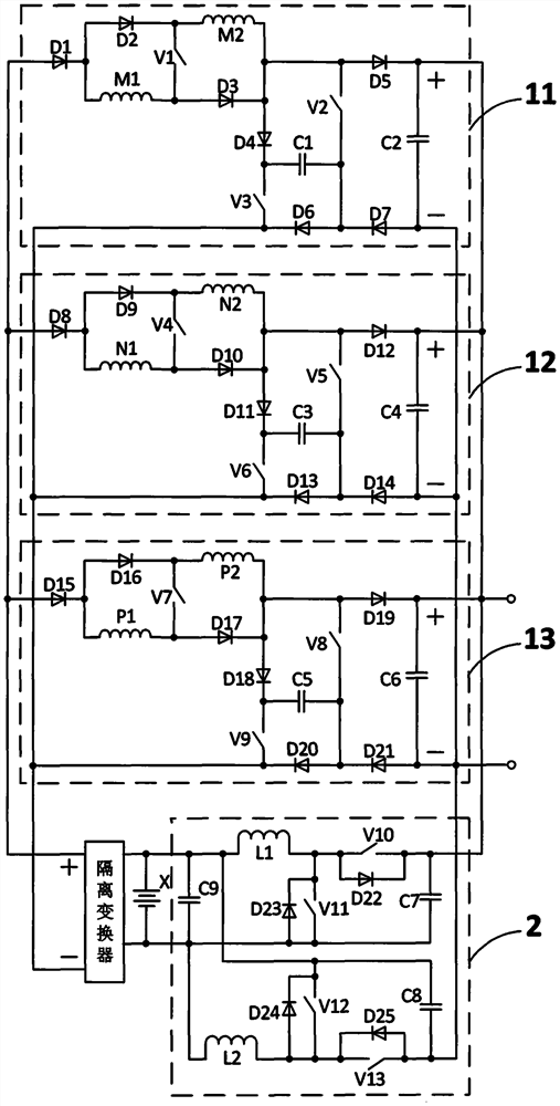
[0030] A switched reluctance generator converter system of this embodiment, as attached figure 1 As shown, it is composed of the first phase winding converter circuit 11, the second phase winding converter circuit 12, the third phase winding converter circuit 13, the double-fed converter circuit 2, the storage battery X, and the isolation converter. The first phase Winding converter circuit 11 inputs positive terminal, second phase winding converter circuit 12 inputs positive terminal, third phase winding converter circuit 13 inputs positive terminal and connects with isolated converter output positive terminal, first phase winding converter The input negative terminal of the circuit 11, the input negative terminal of the second phase winding converter circuit 12, the input negative terminal of the third phase winding converter circuit 13, and connected with the output negative terminal of the isolation converter, the output of the first phase winding converter circuit 11 The ...


PUM


Abstract

The invention relates to a switched reluctance generator conversion system. The switched reluctance generator conversion system comprises a first phase winding conversion circuit, a second phase winding conversion circuit, a third phase winding conversion circuit, a double-fed conversion circuit, a storage battery and an isolation converter. The structures of the various phase winding conversion circuits are the same and are connected in parallel so that the expandability is high, the electric energy from the storage battery is processed by the isolation converter and then serves as one of excitation sources, a special capacitor arranged in each phase winding conversion circuit is used as a second excitation source, each phase winding is divided into two windings in parallel when excitation is performed so as to have a dual-enhancement excitation effect, the double-fed conversion circuit employs a set of conversion circuits to perform flexible charging to the storage battery in a forward direction and feed energy to an output end in a reverse direction in necessity, all the switch tubes of the phase winding conversion circuits are single-pulse wave switching modes, the switching loss is small, and therefore, the switched reluctance generator conversion system is suitable or the field of the switched reluctance generator conversion systems.

Description

technical field [0001] The invention relates to the field of switched reluctance generator systems, in particular to a switched reluctance generator converter with variable power generation voltage, enhanced excitation, double-fed electric energy, low loss and strong scalability, and a control method thereof. Background technique [0002] The structure of the switched reluctance motor is simple and strong, there is no winding on the rotor, and the heat dissipation pressure is small. It has a wide application prospect as a generator, and the converter of the switched reluctance generator is an important guarantee for its normal operation, which is different from the traditional generator. , without a converter, the switched reluctance generator cannot work, so the switched reluctance generator converter system is the core of the normal and better work of the entire system. [0003] The working period of the switched reluctance generator is mainly divided into two stages: exci...

Claims


Application Information

Patent Timeline
Patent Type & Authority Patents(China)
IPC IPC(8): H02P9/00H02P9/30H02P9/38
CPCH02P9/00H02P9/30H02P9/38
Inventor 孙冠群
Owner 浙江知多多网络科技有限公司
Learn More