
Antenna radiation device

A technology of antenna radiation and radiation unit, which is applied in the structural form of the radiation element and the structural connection of the antenna grounding switch, etc., which can solve the problems of high production cost, the size of the antenna vibrator cannot be too large, and the high production cost of the antenna radiation device, so as to reduce the production cost , Increase the antenna bandwidth, the effect of increasing the antenna bandwidth

Pending Publication Date: 2019-07-12
GCI SCI & TECH +1
View PDF0 Cites 3 Cited by
  • Summary
  • Abstract
  • Description
  • Claims
  • Application Information

AI Technical Summary

Problems solved by technology

Due to space constraints, the size of the antenna dipole cannot be too large, and the bandwidth of the antenna radiation device is closely related to the size of the antenna dipole, so limiting the size of the antenna dipole will limit the bandwidth of the antenna radiation device
In addition, the radiating device of the current antenna generally needs to be provided with an additional impedance matching device to adjust the impedance bandwidth of the antenna (for example, a parasitic element for matching and adjusting the impedance bandwidth of the antenna needs to be provided), which will make the production cost of the antenna radiating device high.
It can be seen that the bandwidth performance of the existing antenna radiation device is not ideal and the production cost is high

Method used


Image

  • Antenna radiation device
  • Antenna radiation device
  • Antenna radiation device

Examples


Embodiment Construction

[0045] The following will clearly and completely describe the technical solutions in the embodiments of the present invention with reference to the accompanying drawings in the embodiments of the present invention. Obviously, the described embodiments are only some, not all, embodiments of the present invention. Based on the embodiments of the present invention, all other embodiments obtained by persons of ordinary skill in the art without making creative efforts belong to the protection scope of the present invention.

[0046]In the specification and description of the claims, it is to be understood that the terms "upper", "lower", "front", "rear", "top", "bottom", "inner", "outer" and the like denote The orientation or positional relationship is based on the orientation or positional relationship shown in the drawings, and is only for the convenience of describing the embodiments of the present invention, and does not indicate or imply that the referred device or component mu...


PUM


Abstract

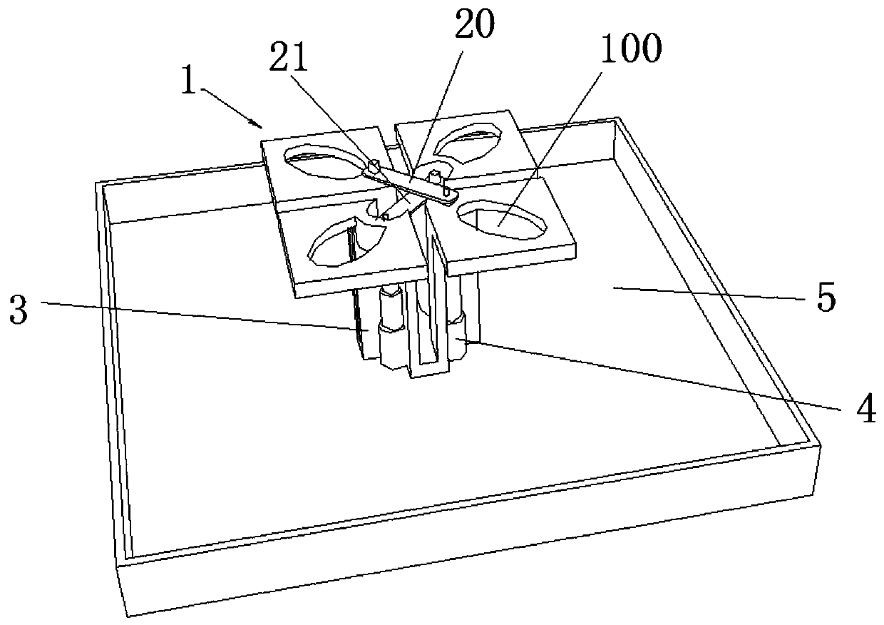
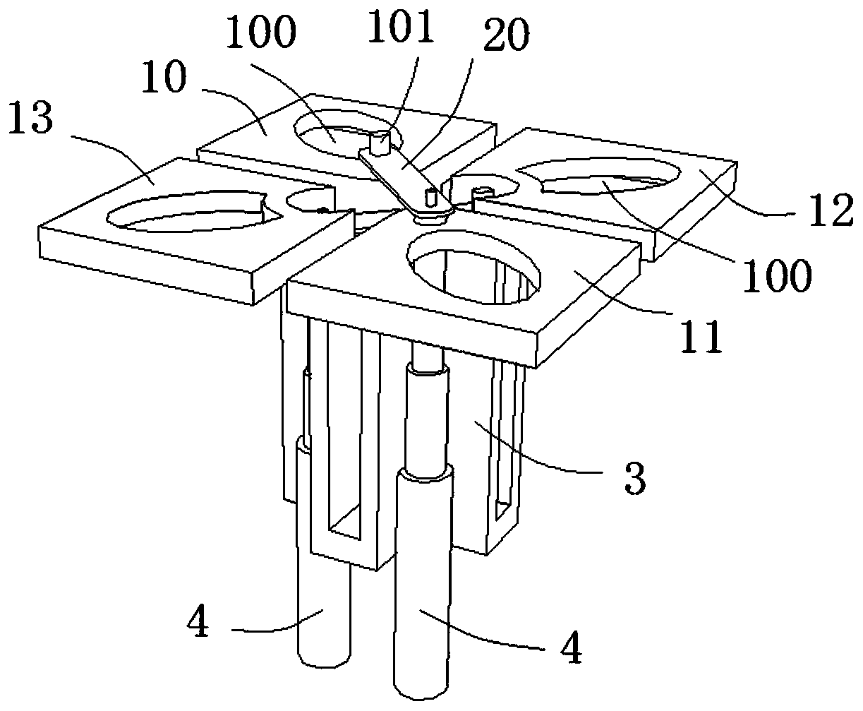
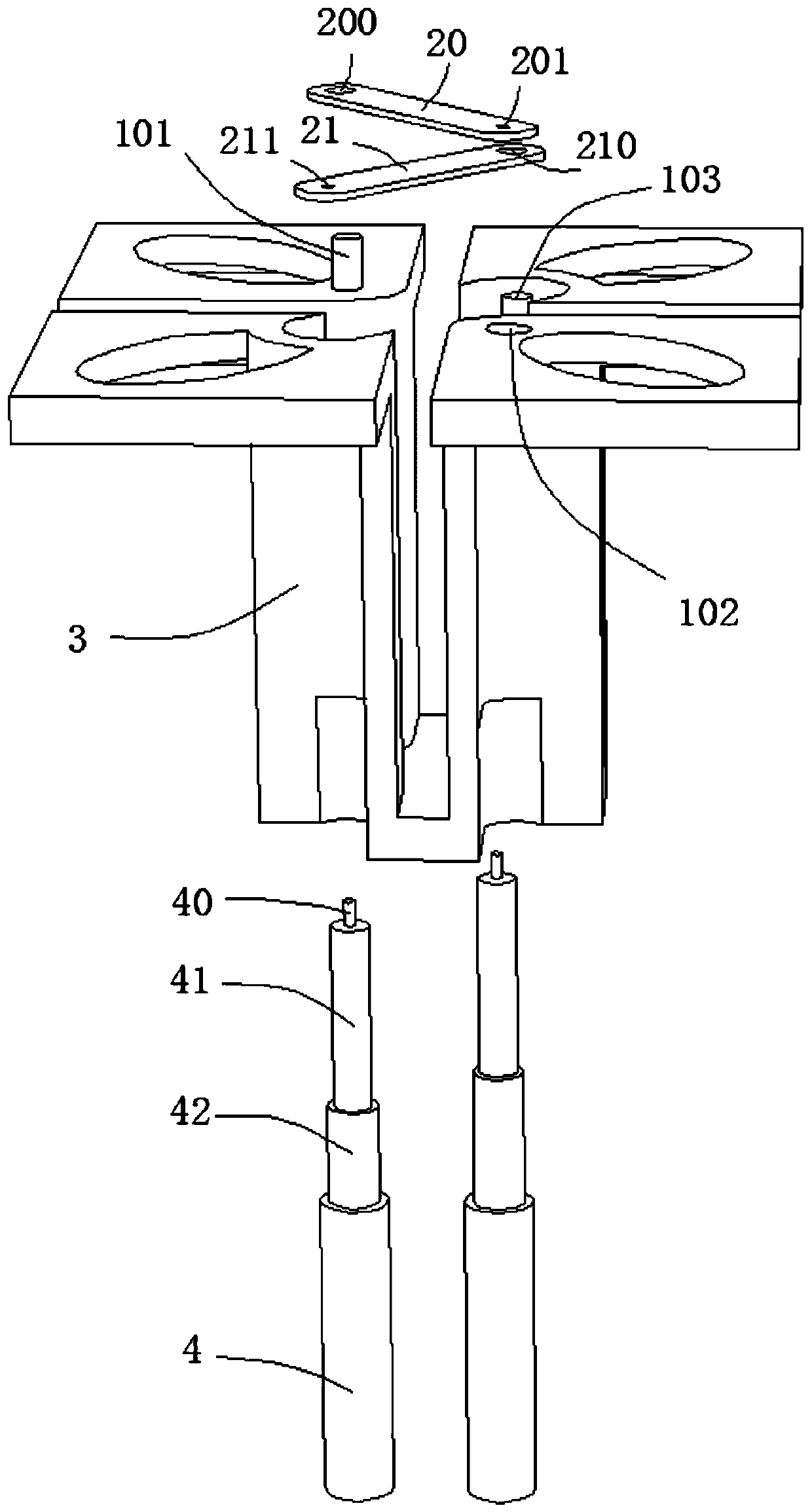
The invention discloses an antenna radiation device. The antenna radiation device comprises: a radiation unit comprising at least one pair of oscillator arms provided with hollow regions and mutuallyarranged at intervals; at least one feed body, wherein each feed body is configured to perform feed for the corresponding pair of oscillator arms; a Balun supporting structure arranged at the lower portion of the radiation unit, configured to support the radiation unit and connected with the radiation unit; and at least one feed cable having one section at the top portion divided into a first subsection, a second sub section and a third sub section in order from top to bottom, wherein an inner conductor of the first sub section of the feed cable is naked and is connected with the corresponding feed body, a dielectric layer of the second sub section of the feed cable is naked, and an outer conductor of the third sub section of the feed cable is naked and is connected with the Balun supporting structure. The antenna radiation device is better in bandwidth performance and low in production cost.

Description

technical field [0001] The present invention relates to the technical field of antennas, in particular to an antenna radiation device. Background technique [0002] At present, the radiation device of the antenna generally includes components such as a radiation unit, a balun support arm, a feed sheet, a parasitic element, and a coaxial cable. Due to space constraints, the size of the antenna element cannot be too large, and the bandwidth of the antenna radiating device is closely related to the size of the antenna element, so limiting the size of the antenna element will limit the bandwidth of the antenna radiating device. In addition, the radiating device of the current antenna generally needs to be provided with an additional impedance matching device to adjust the impedance bandwidth of the antenna (for example, a parasitic element for matching and adjusting the impedance bandwidth of the antenna needs to be provided), which will make the production cost of the antenna r...

Claims


Application Information

Patent Timeline
Patent Type & Authority Applications(China)
IPC IPC(8): H01Q1/36H01Q1/50
CPCH01Q1/36H01Q1/50
Inventor 邹光健陈韶明李伯汝麦世恒潘蓉
Owner GCI SCI & TECH
Learn More