
Antenna

An antenna and sub-antenna technology, applied in the field of communication, to achieve the effect of expanding the bandwidth of the antenna, increasing the resonance path, and improving the isolation between ports

Inactive Publication Date: 2020-07-28
AAC TECH PTE LTD
View PDF5 Cites 0 Cited by
  • Summary
  • Abstract
  • Description
  • Claims
  • Application Information

AI Technical Summary

Problems solved by technology

[0005] The purpose of the present invention is to provide an antenna to solve the problem that the existing antennas cannot realize both wide frequency band and high isolation at the same time

Method used


Image

  • Antenna
  • Antenna
  • Antenna

Examples


Embodiment Construction

[0033] The present invention will be further described below in conjunction with the accompanying drawings and embodiments.

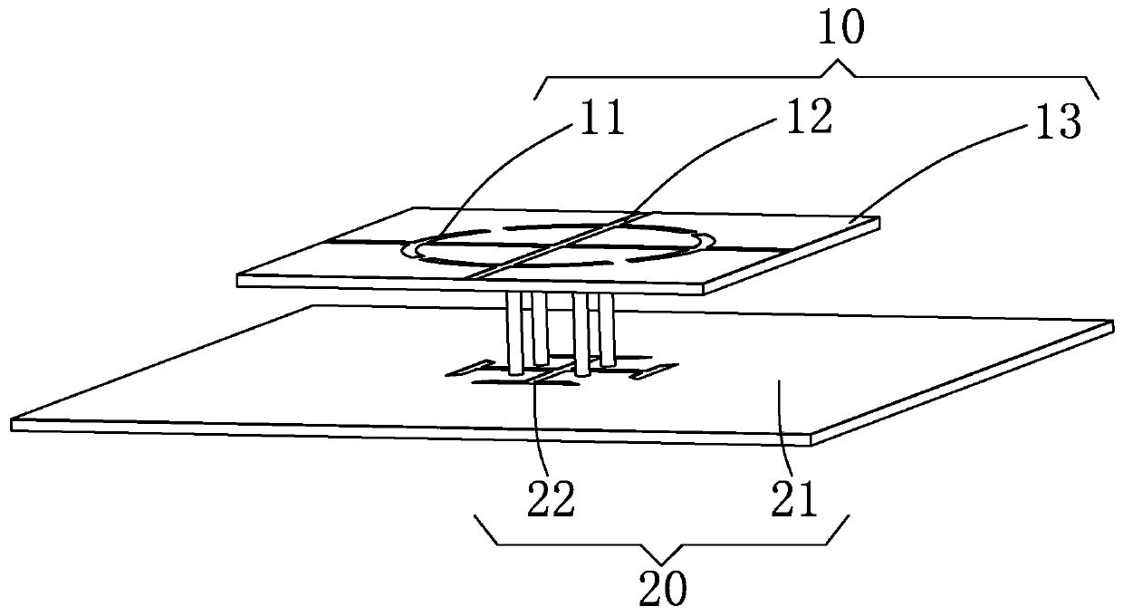
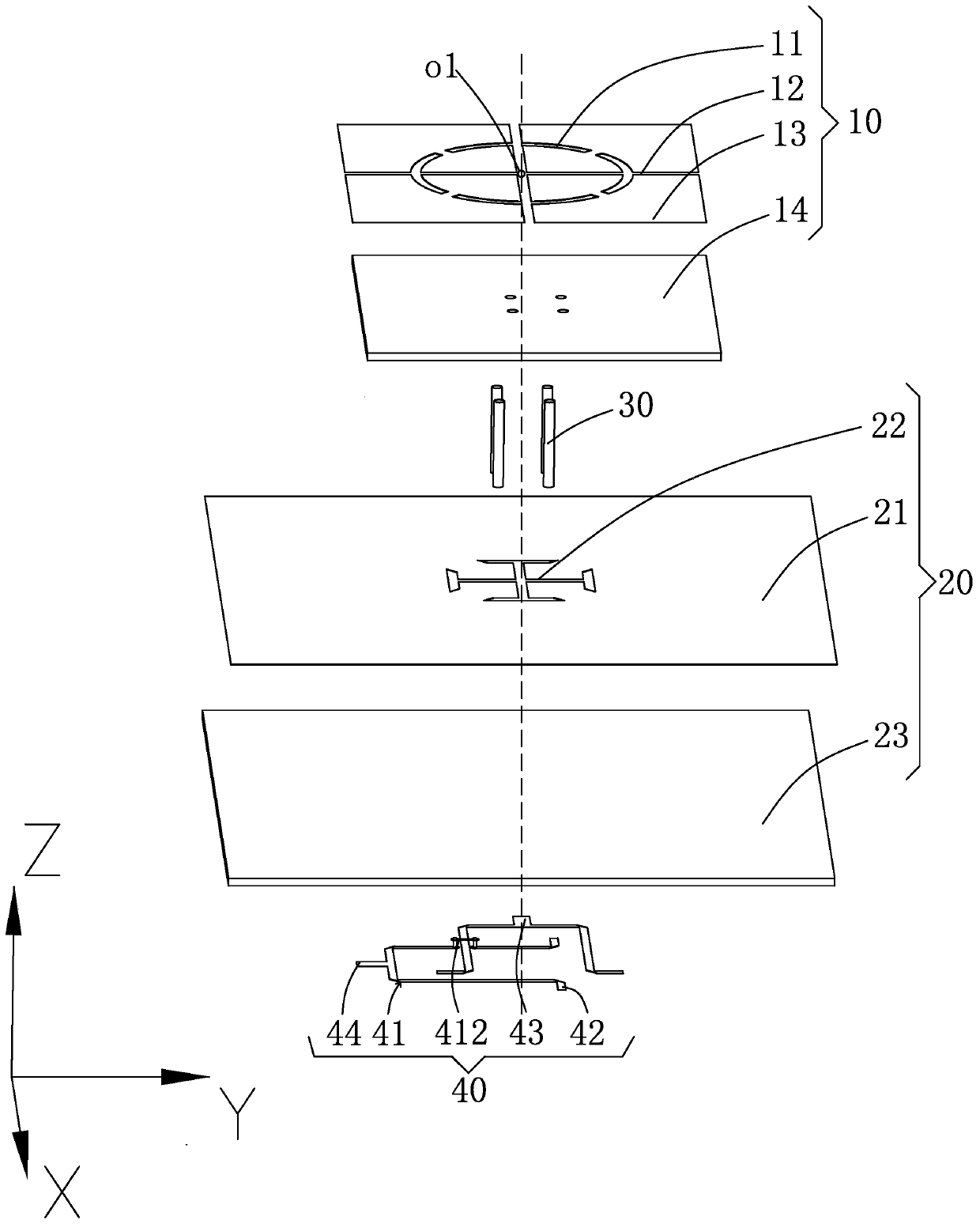
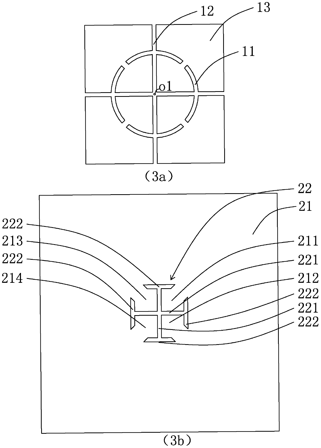
[0034] Please see figure 1 and figure 2 , an embodiment of the present invention provides an antenna, including an antenna radiating unit 10, a grounding unit 20, and a feeding unit 40 ( figure 1 not shown), the antenna radiating unit 10 is provided with several curved grooves 11 and several linear grooves 12. In one embodiment, the number of several linear grooves 12 is two, and the two linear grooves 12 are perpendicular to each other and both Through the antenna radiating unit 10, the intersection point of the two linear slots 12 and the geometric center of the antenna radiating unit 10 (see figure 2 point o1 in ), the two linear slots 12 divide the antenna radiating unit 10 into four sub-antenna radiating units; Spacing distribution, the plurality of curved grooves 11 are used to divide the current lines generated by the four sub-antenna radiat...


PUM


Abstract

The invention provides an antenna. The antenna comprises an antenna radiation unit, a grounding unit and a feed unit, wherein the antenna radiation unit is provided with two linear grooves and a plurality of curved grooves, the two linear grooves are perpendicular to each other and penetrate through the antenna radiation unit, the antenna radiation unit is divided into four sub-antenna radiation units by the two linear grooves, and the plurality of curved grooves are distributed at the periphery of the antenna radiation unit at equal intervals and are used for dividing current lines generatedby the four sub-antenna radiation units. The beneficial effects of the invention are that the antenna radiation unit is provided with the two linear grooves and the plurality of curved grooves, thereby increasing the resonance path, and expanding the bandwidth of the antenna; and the current on the antenna radiation unit can be ensured to flow along the orthogonal direction, and the isolation degree between ports is improved.

Description

【Technical field】 [0001] The invention relates to the technical field of communications, in particular to an antenna. 【Background technique】 [0002] With the arrival of the fifth-generation mobile communication technology, higher requirements are put forward for the broadband characteristics and isolation of base station antennas. MIMO antenna technology is the core technology of 5G (fifth generation mobile communication technology, 5th generation mobile networks) communication. The application of multiple antennas will lead to huge challenges in antenna isolation. The isolation between antenna ports will directly affect the reception of the system. Channel sensitivity and receiver stability. [0003] The methods for improving antenna isolation in existing antennas mainly include differential feeding or hybrid feeding; however, differential feeding increases the difficulty and complexity of antenna feeding network design, and the structure of hybrid feeding is asymmetric, ...

Claims


Application Information

Patent Timeline
IPC IPC(8): H01Q1/52H01Q13/10
CPCH01Q1/523H01Q13/10
Inventor 吕洪辉
Owner AAC TECH PTE LTD
Learn More